Golden motor controller programming cable

Punx0r

1 GW
Joined
May 3, 2012
Messages
5,490
Location
England
Does anyone know how to DIY one of these cables (on the left)?

CruiseControllerProgrammingInterface-PI200.jpg


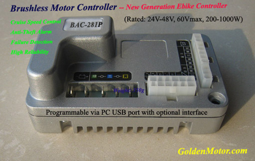
It's for this controller:

Cruise%20BLDC%20Controller.jpg


It's no biggy, but if I can avoid paying $33 and waiting a couple of weeks for delivery then I might as well. I have USB-serial adapters, old USB plugs and then other plug looks like a molex.
 
Looking at this a little more:

On the controller:

red wire goes to T1/5V (throttle 1)
yellow goes to 0V/Z1 (zero)
green wire goes to S2 (spare)
goes to S3 (spare)

USB A pinout is:

Pin Name Cable color Description
1 VCC Red +5 VDC
2 D- White Data -
3 D+ Green Data +
4 GND Black Ground

usb_a_b_female.gif


That seems pretty straightforward except for the which data wire is which. Maybe it doesn't matter? Maybe incorrect polarity won't cause any harm, it just won't work?
 
Punx0r said:
Looking at this a little more:

On the controller:

red wire goes to T1/5V (throttle 1)
yellow goes to 0V/Z1 (zero)
green wire goes to S2 (spare)
goes to S3 (spare)

USB A pinout is:

Pin Name Cable color Description
1 VCC Red +5 VDC
2 D- White Data -
3 D+ Green Data +
4 GND Black Ground

usb_a_b_female.gif


That seems pretty straightforward except for the which data wire is which. Maybe it doesn't matter? Maybe incorrect polarity won't cause any harm, it just won't work?

I would send an email or PM straight to Gary. If someone knows, he will and he's usually good about giving that information up.
 
Ok, this idea is a non-starter :oops:

Someone on youtube has opened one of these cables and the USB end contains a PCB with a bunch of chips on it:

http://www.youtube.com/watch?v=Lcp8K33GccU
 
Oops Cal, I missed your post... Thanks for the tip, but it looks like there's a reason the OE cable costs $30 - it's more than a length of wire.
 
Punx0r said:
Oops Cal, I missed your post... Thanks for the tip, but it looks like there's a reason the OE cable costs $30 - it's more than a length of wire.

Bastards!

Try Gary anyway... maybe he's got a little secret that DIY ESers can use to save a couple bucks. Never know
 
Ah, I bit the bullet and ordered a cable from goldenmotor.ca. It was $33 cdn, but then another 18$ for airmail, plus $5 handling (what?!) for what must be <$5 worth of stamps and envelope.

I'm half expecting to plug the blastid thing in and find the performance settings already maxed out as standard ;)
 
Punx0r said:
Ah, I bit the bullet and ordered a cable from goldenmotor.ca. It was $33 cdn, but then another 18$ for airmail, plus $5 handling (what?!) for what must be <$5 worth of stamps and envelope.

I'm half expecting to plug the blastid thing in and find the performance settings already maxed out as standard ;)


Good luck and let us know how it goes.
 
Well, I finally have some results...

Unfortunately, the 4-6 day airmail took over two weeks to arrive at the UK border. Where customs added another £12/$18 in VAT and (mostly) handling fees. Total cost for the cable was thus $74.

The controller software (downloadable from the GM website) is extremely buggy, often encountering runtime errors and forced closures. There is also very little documentation, seemingly no way to uninstall it, and it will (quietly) refuse to accept half the values you try inputting, despite being within the stated ranges.

This is it:

PI-200 GUI.jpg

Two things worth knowing:

1) The first thing I did was try to load the current settings in the controller. You can't do this, you just get a runtime error. You just have to start changing things. Standard regen is 22%, speed 100%, rpm 92%

2) When you upload any settings, a file called data.mxf is created in the installation folder. Once you exit the program, trying to run it again will cause a runtime error and forced close. You must manually delete this file each time you want to run the program (seriously).

Results:

It won't accept decreased current valve, but will accept any up to the stated limits. However, it makes no difference whatsoever to actual performance - peak current always remains at 25A.

You can turn to the speed down to 50%. It won't accept anything below this.

You can screw with the regen, although you'd have to be pretty brave to turn it much higher than standard.

Some people reported that setting the motor voltage to 24V makes the bike faster. I observed not 0.1mph difference.

The RPM setting is apparently the throttle ramp. Changing it to 100% made no noticeable difference.

The software initially automatically changed the phase angle to 60*. This made the motor stutter a little when first pressing the throttle, it then ran ok. I guess the controller switches to sensorless mode when it sees the problem.


Conclusion: Absolutely pointless waste of time and money on the 48V/1000W kit. I guess the controller itself has capped performance. Someone with a lower voltage/power kit might be able to turn theirs up to the 48V/1000W kit level, as I believe the controllers are physically all the same.
 
I could never work out if changing any of the parameters actually had any effect. I know that someone posted hex edited data files on the GM forum that allowed you to exceed the standard constraints, but I never saw anyone claiming success. If you take a look at http://goldenmotor.com/SMF/index.php?topic=4458.0 there is apparently a new version of the software that has just become available.
 
Thanks for the link, I'll try that V1.1 software tomorrow :)

I was search the GM forum earlier today and that thread didn't come up...

When you click the store/save button, if it accepts what you've changed, it'll quickly flash "upload successful" in the bottom left corner. If it doesn't like the values you've chosen it won't, and the controller will remain with whatever values it previously accepted.
 
The V1.1 of the software has the runtime errors cured. Thanks, Caliban :)

Unfortunately, it still doesn't offer any performance improvement.

I tried turning down the current settings from 30A cont. 50 peak to 25/40 and noticed the bike holding ~20A rather than ~25A on a hill, suggesting a multiplier effect on the settings.

I therefore suspect that the setting is for phase rather than battery current.

However, if someone had a GM 250W or 500W kit then they should be able to turn up the power a fair bit.
 
A pity it didn't have any effect but I suppose that controller is such a dinky piece of consumer orientated tech that it would be asking a bit much for anything very exciting. I was always amazed that something so small was so efficient and (relatively) powerful. I see from the GM site that they are offering a new controller (50A continuous, 100A peak). The form factor is not dissimilar from the old one but whether it is plug compatable or what features are on offer is harder to discern. I have not heard of any reports but I wonder if anyone (Gary, GM Canada?) has any experience with it?
 
I've also seen that on their website :)

I like this little controller, it seems well constructed, small, nice regen, runs cool.

I've just read a thread from 2009 where someone beefed up the (negative?) fet traces with copper wire to get it running at 90A battery. It then died a fiery death at 115A :lol:

I'm half tempted to mod it for 72V/40A rather than just replacing it, but there's little information available, and electronics is not my strong point. I can solder, but I can't trace a circuit like your average controller.
 
Back
Top