Greentime controllers

My kits from Keywin shipped (at least the 24 fet kits) but my order with Green Time has been delayed. We tried to fit 10mm2 wires (7AWG equ) on the boards and it proved to be problematic. Not sure if they will arrive with 10mm2 or if we will need to drop back to 8mm2 - either should be more than overkill.

I have secured silicone end seals for the 6/12/18 fet Infineon controllers :) No more rotting black pig-rubber that crumbles after 15 minutes in the sun.

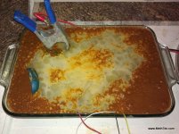
Matthew and I had a chat about using these new 24 fet controllers as an excuse to get a DIY anodizing tank running. I have all the gear to do a serious tank in a 50G 1/2 barrel - just been looking for an application. Results will probably look like a tie dye shirt but that sounds cool to me. My last Electrolysis machine was for rust removal... I dropped a pocket pistol that was rusted solid and got it working again.

View attachment 2
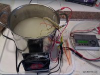
IMG_20110313_125936.jpg
IMG_20110317_170143.jpg

Ok... that is hardly an anodizing machine but an awesome use of the iCharger and same principle.

-methods
 
Found some Rubycon 100v 1000uf got a reply from the seller and there yxa , and that ebay link is the same supplier, Funny
So i see the road to controler modding can be a bit longer than expected if you dont have all the parts / suppliers planed out.
 
I use digikey for everything i can their prices are close to egay and its. Good quality parts. I also get some mosfets from future and mouser but only the three realy i would never trust egay for most semiconductors just maybe some wire and connectors!
 
I ordered some of these for evaluation - 1.5mF 100V in the same space most guys are putting 470uF 200V
These are for the 10mm spaced holes on the battery side of the board

http://www.digikey.com/scripts/DkSe..._go&lang=en&keywords=P6702-ND&x=0&y=0&cur=USD

2.1A ripple current
122mOhm ESR
1500uF 100V
22mm wide
45mm high
3000 hr

I am pretty sure I will be able to fit at least one of these in the 24 fet controllers. I plan to then drill a few strategic holes and just make my own row of capacitors in there... push the leads through the board and jumper over with 12AWG wire. Just get some more capacitance in there.

-methods
 
methods said:
My last Electrolysis machine was for rust removal... I dropped a pocket pistol that was rusted solid and got it working again.

View attachment 1

Ok... that is hardly an anodizing machine but an awesome use of the iCharger and same principle.

-methods

Sorry to continue the offtopicness.. but oh my god, this is just straight 100% pure unadulterated awesome.
 
methods said:
I ordered some of these for evaluation - 1.5mF 100V in the same space most guys are putting 470uF 200V
These are for the 10mm spaced holes on the battery side of the board

http://www.digikey.com/scripts/DkSe..._go&lang=en&keywords=P6702-ND&x=0&y=0&cur=USD

2.1A ripple current
122mOhm ESR
1500uF 100V
22mm wide
45mm high
3000 hr

I am pretty sure I will be able to fit at least one of these in the 24 fet controllers. I plan to then drill a few strategic holes and just make my own row of capacitors in there... push the leads through the board and jumper over with 12AWG wire. Just get some more capacitance in there.

-methods

122 mohm? For 1500uF, 100V? Seems like a pretty crap commutation capacitor to me.

A 470 uF, 100V Rubychon ZL will give you just 33 mohms with 1.89 A ripple in a package that's only 16mm diameter x 35.5mm long. ESR is more important than capacitance in this role.
 
Jeremy Harris said:
ESR is more important than capacitance in this role.

Sometimes I just like them big.... These are not going across the fets these are strapping the input DC on the other side of the shunt where the 10mm holes are and I want to pack in some capacitance. Lowest ESR in the world wont help without some bulk capacitance no? Otherwise we would just hang a 1mOhm 0.1uF on there and call it good.

-methods
 
methods said:
Jeremy Harris said:
ESR is more important than capacitance in this role.

Sometimes I just like them big.... These are not going across the fets these are strapping the input DC on the other side of the shunt where the 10mm holes are and I want to pack in some capacitance. Lowest ESR in the world wont help without some bulk capacitance no? Otherwise we would just hang a 1mOhm 0.1uF on there and call it good.

-methods

It's not like an audio application where you need a lot of capacitance to meet the low frequency, high current ripple, of a lot of bass. You don't need much capacitance to absorb the much higher frequency ripple in a controller, just enough capacitance with a good ESR across a fairly wide bandwidth. In the case of one of these controllers the lowest ripple frequency is going to be the PWM fundamental, which is pretty high (around 15 kHz or so), so what's needed is a combination of capacitors that will give a low ESR from around 15 kHz to the highest frequency component, probably around I MHz at a guess.
 
neptronix said:
methods said:
My last Electrolysis machine was for rust removal... I dropped a pocket pistol that was rusted solid and got it working again.

View attachment 1

Ok... that is hardly an anodizing machine but an awesome use of the iCharger and same principle.

-methods

Sorry to continue the offtopicness.. but oh my god, this is just straight 100% pure unadulterated awesome.

Yeah apologies to all i think im a bit to blame :oops: the willingness of members is real cool though, should have started a thread ive got all my bike sussed sot of but digikey are charging $ for shipping [aus] afaik.thanks to all ill work it out.
And those 24 fet greentime will be worth the wait for sure
 
That makes sense. Clearly I still have lots to learn.... but like hell will I ever do it the easy way. :mrgreen: I have to do it the absolute most difficult way possible so that it sticks. And good call... I was thinking of it like an Audio amp - your argument was perfect and I got slapped down :)

-methods


Jeremy Harris said:
It's not like an audio application where you need a lot of capacitance to meet the low frequency, high current ripple, of a lot of bass. You don't need much capacitance to absorb the much higher frequency ripple in a controller, just enough capacitance with a good ESR across a fairly wide bandwidth. In the case of one of these controllers the lowest ripple frequency is going to be the PWM fundamental, which is pretty high (around 15 kHz or so), so what's needed is a combination of capacitors that will give a low ESR from around 15 kHz to the highest frequency component, probably around I MHz at a guess.
 
Just a quick question about caps, are 'Low Impedance' caps similar to Low ESR types?

I've ordered some Nichicon UPM1J100MDD1TA caps for a controller that had 50v caps, and I'm upgrading it to 63v caps. The datasheet doesn't seem to list the ESR, but I've only got room on the PCB for 5mm diameter caps, would these be any good?
 
Since we are talking about caps....

There are some "end run" Rubycon caps floating around.
Model YXA
You are highly likely to encounter them in the near future. Keywin has a large batch of them and is supplying them with the kits and controllers as an upgrade from the nasty caps that are usually used.

Some digging on alibaba and found this datasheet
http://www.rubycon.co.jp/en/catalog/e_pdfs/old/aluminum/e_YXA.pdf

You can see that they are discontinued - which is why our Chinese suppliers are getting them so cheap and populating our stuff with them. At the moment Keywin has a large batch

100V
1000uF
105C
3000 hours

7.5mm pins, 18mm wide, 30mm tall
So they fit the 24 fets perfectly

From that data sheet I calculated the Ripple and ESR

60hz 0.8 * 985mA = 788mA
120hz 1.0 * 985mA = 985mA
500hz 1.1 * 985mA = 1.083A
1khz 1.15 * 985mA = 1.132A
<=10khz 1.2 * 985mA = 1.182A

And I think I got this calculation right....

tan delta = 0.08 for 100V
@ >1000uF add 0.02, so I am going to do that
So tan delta ~= 0.10 for our purpose (nice round number)

tandelta = ESR / Xc (as found here)

Xc = 1/(2 * pi * 120hz * 1000uF) (I had to use 120hz because that is the frequency tandelta was supplied at right?)
Xc = 1.33

ESR = 0.10 * 1.33
ESR = 0.133 ohms

So for our purposes those would be about 1.2A ripple current and 133mOhms
Not horrible

By comparison
ZLJ:
http://www.rubycon.co.jp/en/catalog/e_pdfs/aluminum/e_zlj.pdf
http://www.digikey.com/product-detail/en/100ZLJ820M18X40/1189-1048-ND/3133977
Rated at 1.12A Ripple

1) Ripple Current = 3.5A (>10khz multiplier times value for 100V in table)
2) ESR = 26mOhms


ZLH:
http://www.rubycon.co.jp/en/catalog/e_pdfs/aluminum/e_zlh.pdf
http://www.digikey.com/product-detail/en/100ZLH820M18X40/1189-1037-ND/3133964
Rated at 2.11A Ripple

1) Ripple Current = 3.86A (Calculated at >10khz)
2) ESR = 26mOhms

So clearly if we want to plop down the cash the ZLH and ZLJ (as suggested by Jeremy H.) have an order of magnitude better ESR and quite a bit better ripple rating

BUT....

When we can source the controllers with (what is probably) a genuine Rubycon cap that is on sale because it is being phased out... that sounds like a good compromise.

I landed by 24 fet kits btw
Up all last night madly assembling with my custom wiring harnesses etc.

-methods
 
Any sign of the Greentime stuff, Methods? Can't wait for you to abuse one and report back.
salute.gif
 
He is responsive to emails but no... I still dont have my samples.

I do have Keywin kits tho - taking pictures for a build thread to help fellas out. This time around I am getting a lot more mid-range capacitance on the board. Board has plenty of 0.1uF and Electrolitic. Sprinkling my favorate 1.2uF caps around - sooo much easier to do it before the traces have been beefed up.

Also acquired a Lyen 24 controller and did a series of shots on how I would upgrade it for higher current.

My only real problem these days is trying to find something to test this stuff with. I am thinking I am going to use a stalled high KV motor for my first round of testing and then some sort of dyno for heat-soaking testing. Any help or suggestions would be welcome - I will start a thread soon.

-methods
 
A set of inductors in a bucket of watter and some light bulbs or stove elements in series with each inductor and a program to send a fake hall signal to the controller to make it think the motor is spinning.
 
Dude... you are on to something there. I can write a quick Arduino code to feed the hall input and then we can drive a short as long as we want! Smart!

To make it simple I could probably just grab an old 9C and tack it in together with some scrap metal and the welder. Maybe leave it a little loose so it can spool up and BANG hahahahaha. Drop it in a bucked of water.

Seriously - though... fooling the halls is a very good idea. If I write the code I will post it up for all - then anyone can just buy a $10 arduino, upload the sketch, and be on their way to short circuit testing.

-methods
 
methods said:
He is responsive to emails but no... I still dont have my samples.

I do have Keywin kits tho - taking pictures for a build thread to help fellas out. This time around I am getting a lot more mid-range capacitance on the board. Board has plenty of 0.1uF and Electrolitic. Sprinkling my favorate 1.2uF caps around - sooo much easier to do it before the traces have been beefed up.

Also acquired a Lyen 24 controller and did a series of shots on how I would upgrade it for higher current.

My only real problem these days is trying to find something to test this stuff with. I am thinking I am going to use a stalled high KV motor for my first round of testing and then some sort of dyno for heat-soaking testing. Any help or suggestions would be welcome - I will start a thread soon.

-methods

Thanks Methods. Unfortunately I can't help. I used to have very agricultural methods, people sitting on a bike, pulling the brakes and the throttle at the same time. Caveman stuff. It takes 10 people to test a bike. 2 to hold it, one to sit on it, another 2 to read what the Cell-Logs are saying and watch for sag, another one to make the tea. :shock:

Very disappointed in Leo. There were always delays with mine but did eventually get them. His after-market support was good too, using the Ali-chat.

I would contribute to a fund if you set one up, I am sure a fund run by you would soon attract enough authority and cash to design and make a custom dyno. I will donate $20 if you want. I believe the forum should have designated, supported testers who are supported by the average, less technically-inclined user.
 
Actually I already approached one of our capable new members about building a dyno. He is a busy guy but there is a good chance that he might be able to come up with something in the next 6 months. As always the problem is time and not design - as I am sure he already has all the details worked out in his head.

This dyno will allow us to test both motors and controllers - or motor controller combo's

-methods
 
Burtie built a load dyno using software and a bldc motor for a load you just hook lightbulbs to one or more phases to add load. I built 2 inita dynos one is for scooters up to ~5 hp and the other is for motorcycles and atv's 5-300 hp. The roller on the big one weighs 640 lbs. i plan to use something to add load to the big one in the future to be able to hold a constant speed. ( I do a lot of performance tuning ). As for the fake hall sensor signal boad make it have a pot to change the rpm so we can use the trottle at different positions and then differen rpm to load test a controller. This. Would be handy for a lot of stuff!!! :)
 
Be careful about hooking CA's to those ordered with CA plugs prior to Aug 1. They went by that old wiring pic on Ebikes.ca and if you use regen it will blow your CA, because the number 6 wire, the throttle over-ride, is connected to the wrong place. I know, because I blew one of my CA's and now have to replace some op amplifier thingies inside.

Also, if you use regen, make sure the braking force actually charges your battery. My 36fet does, but some of the other controllers may not. Make sure you see reverse sag to know it's charging your battery. Apparently the Chinese have actually made some controller boards that have a swithced plug braking and call it EABS. Yes it is electronic anti-lock brakes and yes it feels nice and smooth and works all the way down to a stop, but you don't want it unless your ebike is a low power street legal ebike in Australia or Europe. All that braking energy gets turned into heat in the controller and motor, which can very easily burn them up.

When testing your setup, just use low speed braking at first to make sure you see the voltage increase during regen braking. Don't trust the AMIN to indicate regen is working, because there is a reverse current for an instant. Don't find out the hard way by burning something up like I did to find out.

Everything seemed fine. First, the CA was acting weird, so I ignored that I didn't see reverse battery sag and went for a real ride. I forgot my golden rule of always ride uphill for tests. I got out a couple of miles before I had some space for good speed and hit the brake to slow from about 100kph, and got the double pop of 2 burnt controllers. Not only did I have a long uphill walk of shame, but I didn't bring any tools at all, so I had to push it the whole way with the plug braking effect of mosfets blown in 2 controllers.

I've been able to keep the next pair of controllers alive, but it takes judicious use of the electric braking and it still heats up the motor and controller quite a bit. Using just the mechanical brakes the controllers and motor stay far cooler, so it's definitely this plug braking thing that's the problem.

As I understand, the 24's and 36's are both sensored/sensorless and both have regen that works AND this EABS thing, so just make darn sure you actually have regen before any serious riding with electric braking. Hopefully they figure it out and get a setup where the EABS takes over at very low speeds where regen doesn't work. To me that is the only justification for even having it at all.

John
 
John in CR said:
Be careful about hooking CA's to those ordered with CA plugs prior to Aug 1. They went by that old wiring pic on Ebikes.ca and if you use regen it will blow your CA, because the number 6 wire, the throttle over-ride, is connected to the wrong place. I know, because I blew one of my CA's and now have to replace some op amplifier thingies inside.

Also, if you use regen, make sure the braking force actually charges your battery. My 36fet does, but some of the other controllers may not. Make sure you see reverse sag to know it's charging your battery. Apparently the Chinese have actually made some controller boards that have a swithced plug braking and call it EABS. Yes it is electronic anti-lock brakes and yes it feels nice and smooth and works all the way down to a stop, but you don't want it unless your ebike is a low power street legal ebike in Australia or Europe. All that braking energy gets turned into heat in the controller and motor, which can very easily burn them up.

When testing your setup, just use low speed braking at first to make sure you see the voltage increase during regen braking. Don't trust the AMIN to indicate regen is working, because there is a reverse current for an instant. Don't find out the hard way by burning something up like I did to find out.

Everything seemed fine. First, the CA was acting weird, so I ignored that I didn't see reverse battery sag and went for a real ride. I forgot my golden rule of always ride uphill for tests. I got out a couple of miles before I had some space for good speed and hit the brake to slow from about 100kph, and got the double pop of 2 burnt controllers. Not only did I have a long uphill walk of shame, but I didn't bring any tools at all, so I had to push it the whole way with the plug braking effect of mosfets blown in 2 controllers.

I've been able to keep the next pair of controllers alive, but it takes judicious use of the electric braking and it still heats up the motor and controller quite a bit. Using just the mechanical brakes the controllers and motor stay far cooler, so it's definitely this plug braking thing that's the problem.

As I understand, the 24's and 36's are both sensored/sensorless and both have regen that works AND this EABS thing, so just make darn sure you actually have regen before any serious riding with electric braking. Hopefully they figure it out and get a setup where the EABS takes over at very low speeds where regen doesn't work. To me that is the only justification for even having it at all.

John

For sure, alway talk to leo on skype or alibaba chat, make sure he sets it to regen, and ask for cruise control, 3 speed
switch, PAS, reverse, cycleanalyst plug. I personally dont use CA for the bike build, so you know better.
and all the greentimes are sensor and sensorless capable.
 
I am not sure the controllers are sensored and sensorless capable, Mine only worked in sensorless mode, no matter how I arranged the hall wires from the controller to the motor, it always acted in sensorless mode. The only reason I bothered connecting any hall wires was to get the correct speed on the CA.
 
Back
Top