Greentime controllers

I will have to disagree with John in CR regarding the term EABS meaning a controller wont put regen amps back into a battery pack.
EABS is a generic term that began very early with ebikes in china, some of the larger ebike companies probably going back near 10 years have been using
that term ( electronic assisted braking system: eabs) and my experience has been that in general companies using that term the energy is going back into the
batteries. The term eabs isn't linked to controllers that turn regen energy into heat via windings and mosfets, I have never come across a controller that worked in that way I would think they are very rare.
 
whatever said:
I will have to disagree with John in CR regarding the term EABS meaning a controller wont put regen amps back into a battery pack.
EABS is a generic term that began very early with ebikes in china, some of the larger ebike companies probably going back near 10 years have been using
that term ( electronic assisted braking system: eabs) and my experience has been that in general companies using that term the energy is going back into the
batteries. The term eabs isn't linked to controllers that turn regen energy into heat via windings and mosfets, I have never come across a controller that worked in that way I would think they are very rare.

you would think, but with these greentimes you have to specifically ask for regen. EABS is merely regen but without the charging of the batteries, for greentime controllers.
 
whatever,

The point is be f'ing A careful. Make sure the braking force is actually resulting in a charge going back to your battery. This is the first time I've seen a controller trigger a braking force that wasn't regen, and if it's not charging the batteries then that energy is getting turned into heat right where you don't want extra heat. I'm not saying EABS isn't typically regen, I sure hope it is, but don't assume it is whatever terminology is used. Verify it before doing any serious electric braking.
 
The Mighty Volt said:
I am not sure the controllers are sensored and sensorless capable, Mine only worked in sensorless mode, no matter how I arranged the hall wires from the controller to the motor, it always acted in sensorless mode. The only reason I bothered connecting any hall wires was to get the correct speed on the CA.

Try the blue speed sense wire to pick up a signal for the CA, but verify the voltage on it first. I'd worry about it suddenly going to sensored mode with a bad combo and pop goes the weasel. How is the sensorless BTW? That may be the way to go with my 6 phase motors. It would certainly be easier.

John
 
dnmun said:
how is it possible to have regen and not have charging of the batteries?

where does the regen current go?

Go out to your bike
Disconnect the controller from the motor
Ride it

Feels normal right?

Now tie all three of your motor phase wires together and try to ride it.
lol...

That is called a crowbar brake - the motor tries to generate power into a short circuit so it causes great resistance. I2R heat goes into the fets and the rest goes into the motor. The fets are just turned on 100% of the time and act like a crowbar relay.

This is why you always disconnect a controller after you blow a fet. Fets fail short-circuit so they act like a brake on the motor. To roll freely one must disconnect the controller.

-methods
 
Also -

I got a notification that I received a DHL shipment at my other mail box. I will go pick it up in a day or two - I suspect it is the shipment of samples. I just checked my email - ordered on July 10th. There was a hangup over 10mm2 wire vs 8mm2 wire but shipping time was still triple what Keywin can do it in.

btw: Keywin is back on my good list :mrgreen:
Kenny is back on my Shit List :?
Leo is TBD

Matthew and I spent the last 72 hours straight working out prototypes and build plans for our 24 fets. I started 1 fire and we had two small detonations. At one point I had a motor going in the test stand before I realized that all of the phase A fets were uninstalled lol.

-methods
 
ok so all the hiside and loside mosfets for all three phases are turned on at the same time, overriding the hall sensor inputs, and for regen the hall sensors would still be triggered at the proper time to create the back emf that pushes current back into the battery, but without any pwm, full on all the time.
 
dnmun said:
ok so all the hiside and loside mosfets for all three phases are turned on at the same time, overriding the hall sensor inputs, and for regen the hall sensors would still be triggered at the proper time to create the back emf that pushes current back into the battery, but without any pwm, full on all the time.

If you do that then you crowbar the battery. Nice way to get some fireworks.

Easy way to plug brake is just switch EITHER all the low side FETs on, OR switch all the high side FETs on, with PWM disabled. This just shorts the motor phases together. Not a nice thing to do, as it heats the motor up pretty quickly, as pretty much all the regenerated power gets dissipated in the motor winding resistance.
 
dnmun said:
ok so all the hiside and loside mosfets for all three phases are turned on at the same time, overriding the hall sensor inputs, and for regen the hall sensors would still be triggered at the proper time to create the back emf that pushes current back into the battery, but without any pwm, full on all the time.
Uhm you do realize this is not possible because your controller will be a big ball of lightling mixed with plasma right??
 
John in CR, i'm very appreciative that you have raised this issue with greentime controllers, it is quite a concern.
 
ian.mich said:
For sure, alway talk to leo on skype or alibaba chat, make sure he sets it to regen, and ask for cruise control, 3 speed
switch, PAS, reverse, cycleanalyst plug. I personally dont use CA for the bike build, so you know better.
and all the greentimes are sensor and sensorless capable.

Please define "PAS"
 
flexy said:
Please define "PAS"

Pedal Assist Sensor. It's the sensor that fits to the BB and sends a throttle signal to the controller that's proportional to cadence, meaning you don't need to use a throttle.
 
yeah i was pretty much just listing all the features you can get for little to no extra charge
 
ian.mich said:
yeah i was pretty much just listing all the features you can get for little to no extra charge

FWIW, none of those features are unique to this controller, they are pretty much a standard feature on all the BLDC controllers I've come across on the past few years. Quite a few are user programmable, so you don't have to get a Chinese supplier to do the setting up for you, you can do it yourself in a few minutes, too. Useful if you want to quickly make changes to the spec or setup at some future date. Personally I'd not want to get a controller that wasn't user-configurable, but maybe that's just because I fairly frequently end up swapping controllers around and need to change the settings.
 
Jeremy Harris said:
ian.mich said:
yeah i was pretty much just listing all the features you can get for little to no extra charge

FWIW, none of those features are unique to this controller, they are pretty much a standard feature on all the BLDC controllers I've come across on the past few years. Quite a few are user programmable, so you don't have to get a Chinese supplier to do the setting up for you, you can do it yourself in a few minutes, too. Useful if you want to quickly make changes to the spec or setup at some future date. Personally I'd not want to get a controller that wasn't user-configurable, but maybe that's just because I fairly frequently end up swapping controllers around and need to change the settings.

yeah i know, but i just bought a 18fet 4110 controller for under $80, i'll be able to run 6kw for years and never have to change a controller. i find programmability is somewhat overrated, especially since i figured out how to change the LVC. Though they do plan to have programmability for all their controllers in future.
 
ian.mich said:
yeah i know, but i just bought a 18fet 4110 controller for under $80, i'll be able to run 6kw for years and never have to change a controller. i find programmability is somewhat overrated, especially since i figured out how to change the LVC. Though they do plan to have programmability for all their controllers in future.

Again, FWIW, they actually have programmability right now, but the vendor apparently won't release the programming code, presumably because they want you to buy another controller from them with the new settings rather than let you reprogramme one you already have.

I'm not knocking this, it makes commercial sense in a way to not let users have access to the programming code, but right now there doesn't seem to be anything special about these controllers that singles them out as being in any way better than any others that are around. I'm not even sure that the price is that great, as I think I paid something like $80 for the 18 FET Xiechang I have, although that was around three years ago. I know I bought a couple of Xiechang 18 FET controllers minus FETs for around $30 to $40 each. Even those old controllers can be easily programmed to change the LVC, battery and phase current limits, three speed settings, reverse speed, cruise control settings, regen settings etc.
 
Leo at greentime has mentioned they will try xiecheng at some stage, will probably bump the price up a little bit
but I wouldn't think by much.....just a waiting game.
 
REVIEW PART 1 of 2

Preamble: It should be noted that I spent all day in the hot sun loading and then unloading my trailer, drove 1.5 hours fighting with the wife the whole way, I am tired, angry, and at the moment I have absolutely no tolerance for bullshit. So it is unfortunate timing for Leo that I should have picked up his shipment of controllers on my way into town.

Requirements: Greentime (Leo) is an excellent communicator and we shared about 50 emails. I was pretty explicit in what I asked for. I wanted GENUINE IRFB4110 fets, I asked for the traces to be built up with 10mm2 wires (which we later renegotiated to 8mm2), I asked for the CA tap to be wired properly to the throttle and not to the ebrake, I asked for the current to be set as high as possible (which he stated was 80A). I told him I wanted the best - no expenses spared and I told him my intention to further modify the controller after his initial work to take it up to a 20KW machine.

Shipping: Ordered on July 10th and received about August 6th - one month is a very long turn around for 5 samples... especially for a guy saying that he wants to buy 50 units...

EDIT FROM THE FUTURE: This is an overly harsh review. Turns out the lame looking traces really can handle 80A continuous and the RDSON of the mosfets really is about 4.6mOhms... so these are pretty damn legit. They dont look like it but they are.

What I received: Almost none of the requirements were met. I am extra disappointed since the communication was so clear... my expectations were high. I am used to having to communicate with smoke signals and body smells but Leo speaks perfect English. I knew something had to be wrong else he would be rich by now...

So when I opened the box it looked good at first.

NOTE: IF YOU ARE NOT SEEING THE ENTIRE PICTURE - WITH THE LOGO DOWN IN THE CORNER - TRY A DIFFERENT BROWSER OR INCREASE YOUR SCREEN RESOLUTION. IN CHROME THAT IS THE CTRL button with minus (-)

IMG_20120807_165444.jpg

They are nice small controllers and the packing was good. I liked the look of the heavy gauge wire coming out and the big thick copper ring terminals gave me hope

View attachment 7

IMG_20120807_165526.jpg

Typical garbage white connectors
IMG_20120807_165541.jpg

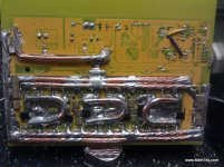
Things started to turn ugly when I dropped the side cover and peeked inside

IMG_20120807_165656.jpg

EDIT FROM THE FUTURE: Did an 80A constant current test and the traces only heated up t0 40C so even though they look pinner they can actually handle 80A continuous.

Clearly those traces are not built up with 7AWG... or 8AWG... or 10AWG, 12AWG, 14AWG, or even 16AWG. Looks like a pair of 18AWG :roll: ala Keywin / Lyen special. Look how far the PCB run is from the red wire to the yellow phase... at the very least it could have been soldered into the middle of the trace by the blue phase. That would give it a chance... but mounted over there and rated at 80A? Phtttt.... wait until I hook this up to my 80A current source and show how hot it gets after just 10 seconds.

IMG_20120807_165904.jpg

Dude... frucking really?
This shows a complete lack of understanding. Why the hell would I want 7AWG wires hooked up to one end of a 10" PCB trace that has only a 16awg equivalent? And how the hell is that trace going to hold up to 80A continuous? No frigging way - unless you dont mind 150C traces and bubbling solder mask.

This is wrong - they could be fake but testing shows that they at least have 4.6mOhms RDSON which means they are close fakes if they are fake. Not garbage fets at all.

Then things rolled further downhill when I realized that the mosfets were counterfeit. I have handled more IRFB4110 fets than anyone on this board - literally tens of thousands... and many other IR parts like the IRFB4115 and the surface mount version of the 4115. There is one thing they all have in common... THE PRINTING OF THE PART NUMBER. It is a very distinct color and texture. It is NOT a stamp - i.e. there is NO IMPRINT left on the plastic housing. It is some sort of laser print or some other non-contact technology (anyone know?) I guess it could be a stamp but I have no recollection of ever seeing a genuine IRFB4110 fet that had imprinted lettering.

These mosfets have the correct housings - all the features look right - but the labels are clearly stamped in - as there is a three dimensional indent where the stamp hit. These are not genuine IRFB4110 fets - every single one of them has a foggy dirty look - like a guy was working on his car and then rubbed his thumb on every one.

I am not saying that I am 100% sure. I am 90% sure. Smells like fish and looks like fish - I just need to taste one with my precision equipment and we will see if it is fish.

EDIT FROM THE FUTURE: Good thing I said 90% :mrgreen: Turns out the real IRFB4110's do have the indentations and I was totally wrong.

IMG_20120807_170145.jpg

Ok - reviewing the pictures some of them look "better" - i.e. the pigment of the stamp looks like the right color... but they still have imprints. Something is off and wrong. Arg - I need to run a test on them. I have all the equipment to test the rdson, drain to source breakdown, gate turn-on, all the normal stuff - we will see if there is a glaring difference.

Ok - Ok... I guess it is possible they are real.... now that I am away from the controller and sitting at home I am second guessing my impression (sigh). Benefit of the doubt until I test them.

Onward.

All of the low ESR caps are mounted poorly - long leads. This is forgivable but will have to be corrected.


IMG_20120807_170043.jpg

I am getting tired here... might have to finish this review later

CA Tap is done wrong


Anyway - bah I am exhausted.

I suspect that John in CR is thinking that the proof is in the pudding and not in the recipe. There is some truth to that - if the controller runs strong and cool who cares what is inside right? From his perspective that is reasonable and it may meet his needs for the electric revolution where he is at. If so these are a super frigging value.

Looking like John in CR was right... but we wont know until we test them.

For me the fact that things are not sound inside the box is a major turn-off... So first I will test it as it is. 100V 80A. If it survives I will either dump all 5 of these on the forum or I will upgrade them to pimp status. At a minimum they need 8awg+ on the traces, increased shunt power handling, standard plugs for throttle, maybe 3spd switch, cruise, etc.

Will have to see... if the fets are bogus that just completely ruins it for me no matter how good they run in practice.

Tomorrow I will try to do part two of the review. Maybe I will be in a better mood :x

-methods

EDIT FROM THE FUTURE: No part of this original review was deleted or modified. I left it as it was to show my bias and my mistakes. I added only what is in RED. I am not scared to be wrong - only scared of not being able to admit it when I am wrong :wink:
 
Here is a peek at one of our prototypes. We moved on from this - but this is along the lines of what I was expecting.

In that version we were using 6AWG on the phase island but since we have switched to a much more clever layout that Matthew came up with that balances the path between all the fets and the phase terminal.

Those are dual 8AWG runs on the traces.
That is a precision 4W shunt in parallel with the stock shunt to make about 500uOhms and 8W power handling
Caps are my favorite ceramic - since then we moved them off the board and onto little surf boards. Too much flexing on the board for reliability

It of course has not been cleaned yet... after cleaning and conformal coating it will look awesome. We are going to start selling beta prototype units in a few days to those who have a Cro and can give us good testing data.

-methods
 

Attachments

  • IMG_20120804_212040.jpg
    IMG_20120804_212040.jpg
    107.8 KB · Views: 2,003
damn yea what a roller coaster.

Looks like you could fit some nice fans in that housing plenty of extra space.


look forward to part 2. Hope it works out im in the market for something like this myself.
 
Can a noob like me possibly get in on a beta?

I'll abuse it.... I promise!
 
I would prefer to sell the beta units to folks who have Cro Motors... I dont think any of the standard offerings will stand up to the abuse necessary. Maybe a fan cooled X5 could take it. I would like to get someone to set the current limit to 200 battery amps and give us some heating info. I am almost positive that we will stand up to stall noise and it is only heating that I am unsure of how to handle. We are considering doing some fan cooling.

-methods
 
Nice first part review, methods, I look forward to the next instalment.

FWIW the FETs look fake to me, but then TBH I could never understand how the manufacturer could import genuine IR FETs to China from the US/Mexico and then retail the complete controller for such low price, so I've always suspected they were knock-offs. Just to not piss off the fanatical Greentime worshippers here, loads of Chinese assembled controllers uses either knock offs or locally made substitute FETs, so this isn't a particular criticism of Greentime.

On the plus side the board layout looks OK, even if the tracks are clearly not up to handling the rated power. Any idea what the core controller chip is and whether or not the programming port is accessible?
 
Hi Methy,

Sign me up for a beta :mrgreen:
I will put in a 10k thermistor and hook it up to the CAv3 + analogger. A 20S 13.5Ah lipo pack should be able to deliver the 200A with ease. How much is that in motor current? 500A?
 
Back
Top