Greentime controllers

I am also into fitting 3 speed switch. I hope it works because i need it. High power and wot without input will make the bike run away from you, hahah. Happened to me. Page 14 i think have pictures. It was cool to read k1 and k2 that if they are connected gives more speed, that i didnt know.

I cut one of the three shunts i had in my 15 fet and it now shows more mercy than before. But sadly no grunt power as would expected. Its winter and I like to save life on my batteries as well as sliding on the road at a minimum.

Weeeii
 
leffex said:
I am also into fitting 3 speed switch. I hope it works because i need it. High power and wot without input will make the bike run away from you, hahah. Happened to me. Page 14 i think have pictures. It was cool to read k1 and k2 that if they are connected gives more speed, that i didnt know.

I cut one of the three shunts i had in my 15 fet and it now shows more mercy than before. But sadly no grunt power as would expected. Its winter and I like to save life on my batteries as well as sliding on the road at a minimum.

Weeeii


What are K1 and K2? Did connecting these give you more current?
 
Thanks for the reply! I actually did some more research and hooked up a 3 speed switch the other day. I didn't get any extra current but it did help me achieve a higher top speed. If I lift the wheel up and go full throttle I can definitely hear the tire spin up faster each time I flip the switch, so I know its wired in there correctly, but it didn't help get a higher peak current. I guess I'll just live with it. Probably don't need the extra acceleration anyways, sure would be awesome thought :D

Did you measure amps with your wheel in the air or did you actually ride the bike / moped in the 100 % mode, it can be that you only see higher RPM of the wheel ( no load ) but not higher amps, but when you actually ride it you might see some difference between 75% and 100 % , I think the 3 speed switch / cable only manipulates the throttle signal anyway, at least with my controller

When I put it in 50 % mode my throttle won't work until I twist it from half way -> full.
Maybe it doesn't take more amps to get the wheel spinning in the air to top RPM because that way it has almost no resistance ( drag, weight, wind etc. etc. ) but on the road it's different.

One thing I personally can't get to work on my 24 fet is regen braking, although I set my LVC for 62 volt and under load the battery is 64-68 volt most of the time, maybe that is worth a topic on it's own, it took me one and a half day to not get it to work :? , other than that, a dang fine controller for the money.
 
Truusje79 said:
Thanks for the reply! I actually did some more research and hooked up a 3 speed switch the other day. I didn't get any extra current but it did help me achieve a higher top speed. If I lift the wheel up and go full throttle I can definitely hear the tire spin up faster each time I flip the switch, so I know its wired in there correctly, but it didn't help get a higher peak current. I guess I'll just live with it. Probably don't need the extra acceleration anyways, sure would be awesome thought :D

Did you measure amps with your wheel in the air or did you actually ride the bike / moped in the 100 % mode, it can be that you only see higher RPM of the wheel ( no load ) but not higher amps, but when you actually ride it you might see some difference between 75% and 100 % , I think the 3 speed switch / cable only manipulates the throttle signal anyway, at least with my controller

When I put it in 50 % mode my throttle won't work until I twist it from half way -> full.
Maybe it doesn't take more amps to get the wheel spinning in the air to top RPM because that way it has almost no resistance ( drag, weight, wind etc. etc. ) but on the road it's different.

One thing I personally can't get to work on my 24 fet is regen braking, although I set my LVC for 62 volt and under load the battery is 64-68 volt most of the time, maybe that is worth a topic on it's own, it took me one and a half day to not get it to work :? , other than that, a dang fine controller for the money.


I did measure the current while riding. I repeatedly went to full throttle at each setting,along sure to put the max load on the motor.
 
Hi guys, a while back I purchased two 15fet controllers off Leo but so far neither have worked in sensored mode. I have tried all 36 hall/phase wire combinations but my motor still cogs like mad on start up and under load at low rpm. I'm using a 5055 190kv outrunner with ss411a sensors installed which worked very well with a cheap 18fet sensored only controller from ebay, so I'm having great difficulty figuring out why the 15fet greentime won't work with hall sensors. I have tried contacting Leo through email numerous times throughout the last few weeks asking for possible solutions but I still have not received a response. Can anyone explain why my controllers won't run in sensored mode?
 
ensure all connection is well connected. as my 3 types greentime purchsed different date . all work well with a normal 48v 1000w hub motor.it could be the halls are not adjusted in right position. have u try sensorless?
 
dgrdan93 said:
Hi guys, a while back I purchased two 15fet controllers off Leo but so far neither have worked in sensored mode. I have tried all 36 hall/phase wire combinations but my motor still cogs like mad on start up and under load at low rpm. I'm using a 5055 190kv outrunner with ss411a sensors installed which worked very well with a cheap 18fet sensored only controller from ebay, so I'm having great difficulty figuring out why the 15fet greentime won't work with hall sensors. I have tried contacting Leo through email numerous times throughout the last few weeks asking for possible solutions but I still have not received a response. Can anyone explain why my controllers won't run in sensored mode?

How are they set up 60° or 120°? The controller may be set at the other. Have you checked it with an ebike tester to make sure the halls are functioning properly?

FWIW, it is absolutely never necessary to try 36 wiring combinations. Whoever started that should be taken out and flogged for all the time and frustration it has created for others. Keep either your halls or phases static, and try the 6 combinations of the other. You will get a valid combo in those 6 attempts or something else is wrong. If the valid one is reverse, then swap 2, only 2, any 2 of the wires you were keeping static and find go back to the others and find the right combo of the remaining 5. That makes it and absolute maximum of 11 tries. I've learned some further shortcuts, but I won't confuse the issue with them. Every hall combo has exactly one valid phase combo, and every phase combo has one valid hall combo. Of the 6 valid combos 3 are forward and 3 are reverse, PERIOD. That's "period" used in the proper manner, not like used by a lying politician.
 
It would be nice if phases and halls had numbers, 1,2,3 like AC three phase motors to indicate rotation order instead of just colors. Or letters A,B,C; a,b,c etc. How do you check/ change 60 and 120 degree timing. I am not finding much information on that. Ebike checker sounds like a good device to have in the tool box. I got my gng motor very hot having it wrong when trying a few other controllers. It only sounded a bit louder. Hopefully I did no long term damage
 
Sorry for being a bit unclear, my motor does run sensorless but cogs badly as I stated before. Plugging in the hall wires makes no difference to how the motor runs or starts up. Will the controller attempt to run sensored even if an incorrect wiring combination is used? Or will it continue sensorless?
How are they set up 60° or 120°? The controller may be set at the other. Have you checked it with an ebike tester to make sure the halls are functioning properly?
I'm a bit of a noob at this stuff. My motor has 14 poles and I have spaced the halls to 17.14° mechanical, so I'm not sure weather this is 60° or 120°. Using a voltmeter each of the halls output 2.5v average when the motor is spun so I assume they are all working correctly.
To simplify things I will test the controller on an old 9c hub motor and see if it runs in sensored mode.
 
I have been doing my head in with a simalar problem of not been able to get a greentime controller to run sensored mode and i have managed to isolate mine to been 1 hall sensor been out of timing due to replacing 1/3 of the hall sensors. If you have replaced one you will have to go back and replace all 3 to the same type of hall sensor.

Have you tested your hall sensors are working properly? Get a cheap multimeter set it to read 5V DC and with the controller powered up and the wheel off the ground so you can move it by hand. With everything connected put the negative meter wire to the black hall wire(from the back of the plug works well) and then put the positive meter wire to each of the hall sensor wires, they should jump between almost 0V and 4+V as you move the wheel SLOWLY, you should see solid on/off points if they stay around 2.5V the whole time then something is probably wrong.


With getting regen working on a 24Fet, solder a 20k variably multi multi turn pot accross the resistor that is there and then just start at 0 and go all the way thru it with half turns untill the regen is activated by the 12V input on probably the purple wire(i have to look when i go home as i am not sure on the color) Once you have found the right spot just hot glue or something the pot so it does not change. :mrgreen:
 
I have just got one of the 4110 24 fet greentime controllers,
Can anyone post a picture of the wiring connections?

I think I have figured it out, but I am not sure what the brown/black and pink/black, white/black and single yellow wires are for.
 
Well if anyone could help me out, I would appreciate it.
Edit from the future: I have updated this as information is posted by others, to make a clear connection guide for others

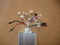
yesterday I was able to test at 48v, sensorless.
it started and ran fine. But I want to know what the other wires are!
For good reason- I want to try the re-gen and reverse. (this is for a go-kart for err... my kids :)


I wish Leo Liu would include a wiring diagram as std, it would be a big help.


This is an edited/ updated copy and paste from Knighty: (thanks dude!)

http://endless-sphere.com/forums/viewtopic.php?f=30&t=40900&start=500

CODE: SELECT ALL
Resistance to Resistance to
thick black thick red Function

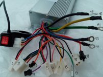
Thick wires **confirmed**
Red - 0 Battery +
Yellow 9k24 - Motor phase
Green 9k24 - Motor phase
Blue 9k24 - Motor phase
Black 0 - Battery - / Gnd

5 wire connector
Red - - 5V hall sensor power
Yellow 4k13 - Hall sensor signal
Green 4k13 - Hall sensor signal
Blue 4k13 - Hall sensor signal
Black 0 - Gnd

3 wire connector **confirmed using 5k pot**
Red - - 5V throttle power
Green 10k - Throttle signal
Black 0 - Gnd


yellow single - high level e brake
black/white -low level ebrake. Yellow is high level E-brake. Sending from about +9V up to pack voltage will activate.
White/blk is low level e-brake. ie short the 2 together which is simply shorting white to
ground activates it.

pink and black- cruise control

brown and black- reverse

Orange /blue / black - three speed.
For the 3 speed, verify that black is ground. Then nothing connected is one speed. Shorting blue to ground is another speed, and shorting orange to ground is the third speed. Which is which speed for low/med/hi is determined by how it was programmed, so test it. This could be handy for a kids vehicle using a hidden 2-way switch, since you might want to govern the speed for them, or for certain riders.**thanks John in cr for the above four updates **

2 wire Red/Purp **confirmed***
Red - 0 Key switch power (Battery +)
Purple 22k - Key switch input

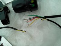
finally- black connector with green/yellow/white/black/blue/red = cycle analyst connector. **thanks Crossbreak**
green: throttle in
yellow: speed signal (hall from motor)
white: shunt+
blue: shunt-
red: Battery+

pink and black- cruise control.
 

Attachments

  • id pho 005.jpg
    id pho 005.jpg
    117 KB · Views: 3,543
finally- black connector with green/yellow/white/black/blue/red = alternative hall connector? programming for uC?
This is a CA plug:
green: throttle in
yellow: speed signal (hall from motor)
white: shunt+
blue: shunt-
red: Battery+

Sorry I can't help you with the rest, my 24fet doesn't have them.
 
Brown/blk is reverse.

Yellow is high level E-brake. Sending from about +9V up to pack voltage will activate.
White/blk is low level e-brake. ie short the 2 together which is simply shorting white to ground activates it. I don't know what regen or plug braking option you have, but at a minimum the ebrake will cut power. It's a good safety item.

Yes, pink is for cruise, so don't connect that for a kids cart.

For the 3 speed, verify that black is ground. Then nothing connected is one speed. Shorting blue to ground is another speed, and shorting orange to ground is the third speed. Which is which speed for low/med/hi is determined by how it was programmed, so test it. This could be handy for a kids vehicle using a hidden 2-way switch, since you might want to govern the speed for them, or for certain riders.
 
cool, thanks for the pinout of that. raises some interesting options! :D
anyone know what the other plugs do?
 
ian.mich said:
oh crap, i forgot. i highly doubt raising the LVC will activate regen, as a 60v LVC will activate regen at 84v.
(LVC voltage)*1.2/(x+1.2)=3
That is the equation. LVC occurs when the whole thing equals 3. the x represents the value in kohm that you replace RJ15k with.
The location of RJ15k can be found in the PDF file layout of the board, it is near the VCC. That is the 15fet board with 75v fets in the PDF. But, I cannot take credit for this. stewrobb gave me the equation.
I want to use this equation but I do not understand what the * means in the equation?
 
Hi Guys! help me understand! that connects to the controller numbers greentime
http://www.aliexpress.com/store/product/Free-Shipping-48V-1000W-45Amax-BLDC-motor-controller-E-bike-brushless-speed-controller-compatible-for-sensor/313864_497637202.html
 

Attachments

  • kontroller 2.jpg
    kontroller 2.jpg
    77.6 KB · Views: 1,522
  • ruchrf.jpg
    ruchrf.jpg
    53.1 KB · Views: 1,522
Tundra, I hope by sorting out the wires for my controller, it helps with yours. The colours of the wires look to be almost the same.

Brown/blk is reverse.

Yellow is high level E-brake. Sending from about +9V up to pack voltage will activate.
White/blk is low level e-brake. ie short the 2 together which is simply shorting white to ground activates it. I don't know what regen or plug braking option you have, but at a minimum the ebrake will cut power. It's a good safety item.

Yes, pink is for cruise, so don't connect that for a kids cart.

For the 3 speed, verify that black is ground. Then nothing connected is one speed. Shorting blue to ground is another speed, and shorting orange to ground is the third speed. Which is which speed for low/med/hi is determined by how it was programmed, so test it. This could be handy for a kids vehicle using a hidden 2-way switch, since you might want to govern the speed for them, or for certain riders.

Thanks for explaining how to connect and activate those functions. I will update my wire colour / connection post to include this info.
 
I have the 36 fet 4110 controller and they programmed it for me at 150A, but I only see max 50-60A at and with 3 way speedswitch at 1 and 2 only less ofcourse.

Is it possible to "fake" the shunt to get higher amps ? I really need about 150A peak and that should be ok for this 36 fet controller.

Maybe they programmed it at 150a phase current ?

Anyway, is there a solution to get it to 150A ?

Thanks
 
This is new for me, I will open it up and check inside. You expect only one shunt ? And how to double or trippel the current ? Any idea ?
 
Is it ok to solder a wire in parallel to the shunt ? Or add some solder ?
 
Bazaki said:
Is it ok to solder a wire in parallel to the shunt ? Or add some solder ?

Parallel wire is good as it conducts better than solder.
 
Back
Top