hall effect sensor help

wallypedal

100 mW
Joined
May 16, 2011
Messages
47
Location
Torrington, Wyo 3 hrs away from a LBS
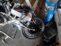
I have a 500W 36V front hub brushless motor from e-bike kit, 3 years old. Parked it when it started stuttering after 3 months use.

I want to know which hall sensors to get from where in order to replace the set. Think I've read every post on most of the ES and others, lots of info on how to change them. Not so much on where to buy, and which specific ones to get. Help? I'm new at working on these things, but pretty handy and systematic. Had the motor apart a couple times. On one of the bearings I can detect a little roughness or a bump, more than I'd like to know is there. Source for these bearings?

Thanks all!
Wallypedal
 
wallypedal said:
I have a 500W 36V front hub brushless motor from e-bike kit, 3 years old. Parked it when it started stuttering after 3 months use.

I want to know which hall sensors to get from where in order to replace the set. Think I've read every post on most of the ES and others, lots of info on how to change them. Not so much on where to buy, and which specific ones to get. Help? I'm new at working on these things, but pretty handy and systematic. Had the motor apart a couple times. On one of the bearings I can detect a little roughness or a bump, more than I'd like to know is there. Source for these bearings?

Thanks all!
Wallypedal
Hey Wallypedal! First things first, follow these instructions:
Welcome to ES 1.jpg

Ok, what you probably need are Honeywell SS41 Hall sensors. PM Icewrench and see if he has any left.
http://endless-sphere.com/forums/viewtopic.php?f=31&t=45577

If not, you can get them from here:http://www.mouser.com/ProductDetail/Honeywell/SS41/?qs=/fq2y7sSKcK/%2bhfJuO3wrA==

Or get Chinese knockoffs on ebay.

BUT......

Why do you think you need them?

As for the bearing you need to get a number from the side of the bearing and post that number so we can know what one you have.

:D
 
Hall sensors don't normally go when the bike is standing still. I think I'd tighten my phase connections and chech the motor connections before opening the motor to replace the halls. Could water have got into your motor while it was laid up.
 
What did a test of the suspect Hall sensors reveal? Jumping to the conclusion of needed replacement without 1st qualifying their condition might waste a lot of time & resources.

http://www.ebikes.ca/learn/troubleshooting.html

Direct drive motor bearings are fairly common size, I don't remember or have any part numbers handy but remove an old one and Google the number found on it. Or, measure with calipers and search by dimension.
 
Thanks to all who replied so far.
- I joined and started posting questions concerning this setup over a couple years ago. I did just add profile information. I live in Wyoming, I think there is an ebike shop in Casper now, didn't used to be.

-it didn't just happen, it happened at least 2 years ago and we yanked the motor then. The motor started stuttering and clicking some at slow speed and takeoff. I just now started working on it again, got a new controller and throttle and set up a bench test arrangement. Connections are good! This did not happen as a result of being parked, it got parked because it happened.

- Now after running it up about half speed, if more throttle is applied it does a major clunk, runs some more and clunks again. If held at half throttle without trying to accelerate, it doesn't clunk. It is also noiser when starting, but will start from zero rotation. This clunk thing is so distinctive I'm hoping others have experienced it.

- I like fixing things, learning new systems, and understanding how and why things work. I am only suspicious of sensor issues because of what I've read here and seen in youtube examples - along with making sure all the connections and wires are good, the battery is charged, the new controller and throttle are in place. Presently researching sensor testing (wish I had that device!) both assembled and dis-assembled. I honestly don't mind multiple take apart put together sessions!

- All apart, I noticed a few things: first, the bearing in the non power side cover is a little clunky feeling when I spin it on my finger. I prefer feeling nothing but smoothness. Second, there are very slight rub marks on 4 or 5 of the stator surfaces, and something that looks like white paper crumbs on the corners of some of them. Not many. Sort of like some of the wire hold down sticker came loose and got chewed up - but it doesn't look like enough to be a factor. Third, the wires going to each sensor have shrink wrap or insulation where each is bent at the base of the sensor. The very outside one doesn't appear damaged, yet is flatter and looks like it was rubbed a little or squashed.

- I'm going to do a little more continuity testing with phase and sensor wires while it's apart, then assemble and try running again. It appears one of the easy tests without an actual tester is to just disconnect one sensor at a time. If no change, same probs then sensor and sensor circuit is suspect. If it changes or doesn't run at all, then that sensor circuit is good = do I have that right?

My shop is not at my home, need to get the bearing numbers, not too worried about finding bearings.

Again, thanks for the input and advice!
 
Did you read the Hall troubleshooting from the link I posted? That will explain how to test Hall sensors. Lifting power to each sensor would only be useful if something was pulling +5V supply down.

Pretty good thread here:

http://endless-sphere.com/forums/viewtopic.php?f=3&t=56423&hilit=+hall+phase+combo

Another one:

http://endless-sphere.com/forums/viewtopic.php?f=2&t=48311&hilit=+hall+phase+combo

My personal journey doing pretty much what you’re asking about:

http://endless-sphere.com/forums/viewtopic.php?f=8&t=48114&hilit=+wire+ptfe

I couldn’t find it but there’s another thread where the guy burned MOSFET’s inside the controller from pushing it with incorrect hall/phase timing or a bad sensor. Don’t create more work for yourself.

I wouldn’t attempt much in the way of repair without a power meter. It can reveal a lot in regard to bad combinations.
 
Ykick Thanks! I will read all you posted and follow your advice. I'll let you know...My meter doesn't have alternate sockets for probe wires like V? Hz slot for the red probe illustrated. I'm assuming that slot is for voltage measure functions, and my meter just let's me switch to that. Been reading the excellent troubleshooting thing. Hidden in the last paragraph of sensor replacement is how to test sensor output before motor assembly. Great!!
 
Did the bench test of the sensors out of the case. They tested good. 5 or 6 of the magnets had something stuck on the surface. Got the light right and detected where the stator and magnets had done some rubbing - making me more suspicious of the bearing. New bearing going in after cleaning everything up. We'll see. The bearing is a 6202RZ,,,made by W&Z evidently.
 
I got a new bearing, cleaned it all up and installed. Bench tested and it started and ran so smooth!! So smooth I didn't notice it was running backwards. :cry: :cry: I turned the fork around and ran it backwards for a while - but it would just stop under load. Wait a few seconds and it would go again.

Thanks for the help so far. I tested the sensors again after assembly, and they were cycling up and down to 5 volts just like the troubleshooter says. Advice?
Wallypedal
 
The chart provides steps to reverse motor electrically.

What's the battery situation? How much current does the motor draw no load?
 
Ykick said:
The chart provides steps to reverse motor electrically.

What's the battery situation? How much current does the motor draw no load?

I guess the chart is somewhere in the links you provided earlier? I'll look. The battery is charged up, showing 39 volts. Current available to halls is 5 volts. Not sure how to test for actual load draw but I'll start trying to find out. Don't have a cycle analyzer, just two or three multimeters.

thanks again :?
 
What does battery voltage do when motor stops under load?
 
Ykick said:
What does battery voltage do when motor stops under load?

I'll be back at it tomorrow, and check that. A question on the phase and sensor combo potentials. (I found the charts, pdf's, and spreadsheets. Also the pic from the troubleshooter. If you have the motor apart and verify the wire colors going to each location for both phases and sensors, does that help the process? Will the sensors reset, cycle, fire regardless of rotation direction? This thing really has the torque on take off right now, albeit backwards. The sudden power drop after putting more load on bugs me. When I pulled a magnet by the sensors, it seemed like they would reset or drop back from their max voltage when moving the magnet one direction, but not always when going the other. Leave it to me to discover weirdness. Still happy that the bearing change and cleanup of magnets fixed the noisiness totally.
Wallypedal
 
wallypedal said:
I'll be back at it tomorrow, and check that. A question on the phase and sensor combo potentials. (I found the charts, pdf's, and spreadsheets. Also the pic from the troubleshooter. If you have the motor apart and verify the wire colors going to each location for both phases and sensors, does that help the process? Will the sensors reset, cycle, fire regardless of rotation direction? This thing really has the torque on take off right now, albeit backwards. The sudden power drop after putting more load on bugs me. When I pulled a magnet by the sensors, it seemed like they would reset or drop back from their max voltage when moving the magnet one direction, but not always when going the other. Leave it to me to discover weirdness. Still happy that the bearing change and cleanup of magnets fixed the noisiness totally.
Wallypedal

I don't think it makes any difference what colors are wired to what phase/hall (A, B, or C) inside the motor. As long as you work through the chart you will find a good combination and then be able to reverse the motor by swapping a couple of wires.

Passing a magnet over the sensor with your hand is not nearly as precise as the motor magnets when assembled. To verify their operation with volt meter on the Hall signal wires everything connected and controller powered on I would just spin the wheel. That should indicate measureable switching voltage signal no matter which direction you turn the wheel of a DD (direct drive) motor.


It sounds like a BMS is shutting the battery down or there's an overcurrent protection inside the controller. Clip a meter on the battery leads and note the battery voltage as you apply more power/load. You're looking for significant voltage drop and/or a complete cut off.

You've never provided any details about the battery - What chemistry? Does it have a BMS? Details that help you help yourself... Pictures would also help us better help you.
 
The battery is from e-bike kits, 12 AH 36 V LiFePO4. I did the hall check again spinning by hand after assembly and they were all switching up and down OK. Will check again today. As in the tutorials, I'm going to set up to test with a 5 A inline fuse and do the 36 possibility spreadsheet. The controller is the 750 W brushless from escooterparts. I'll put a meter on the battery and look for drop as well.

Well, all I had was a 3 amp fuse. Wheel spinning hall sensor check was all good. I swapped a couple phase wires and got proper rotation - I held the wheel and gave it some throttle and blew the fuse. So my next question - what sort of amp draw should I expect and what is the proper amount for protection on most systems? Also, when looking at battery load/draw, can you just continually check available voltage between battery + and - , looking for change as throttle is applied? Am I likely to find several forward combinations that accelerate OK no load, but have big differences in draw under load?

Thanks again,
Wallypedal
 
If it spins smoothly no load and doesn't blow 3A fuse that's most likely a good combination. Once a load is applied the current will normally jump up to around 20-30A and obviously 3A fuse isn't going to cut it.

No load and 3A fuse blows? That's probably a bad combination. This is where a power/Watt meter comes into play. You can better see what is going on in regard battery power, or lack of.

A no load spin with correct Hall/phase combination will draw about 2A.

Has the battery been sitting all this time not being charged? If so, there may cells suffering which might explain the power cutoff when applying load to the motor. Leave it on the charger even if the light is green - it can sometimes take days for cells to balance if there's not irreversible damage.

Do you have 3 or 4 SLA batteries around that can be wired up to bench test the system and eliminate the possibility of your EBK battery pack BMS cutting off?
 
Not your Hall sensors......Good news because replacing them is a major PITA.

As for the fuse, go to the auto parts store and get a fuse, (I prefer the blade style fuse)...25 amp if they have one. And if that one blows then try a 30 amp. If they don't have 25 or 30 go with a 40 amp and that should not blow on your setup. But try the smaller ones first to protect your setup.

To fully know how many amps your system is pulling, you will need a watt meter (or ammeter). Inexpensive rc watt meters can be found on eBay.....

Your battery voltage fully charged should be 43.8v, so if your battery is only charging to 39v you now have 3 more things/systems to check.....

Check:
1: Your charger to see if it is giving you enough voltage to charge your pack properly.
2: All your cells to see if they are each getting up to 3.65v apiece. (3.65v X 12 cells = 43.8v)
3:Your BMS to see if it is charging all cells properly.

Meter your charger, is it giving at least 43.8v on the output? If no, your charger is a problem. Some chargers don't kick in until they since a low voltage to your pack. You may have to leave the charger on the battery pack for a while so the charger kicks in.

If your charger is giving at least 43.8v leave your pack charging over night and check it in the morning with your digital multi-meter.

Is the pack, once off the charger reading about 43.8v? If yes, you are good to go, if no, you will need to check all the cells in your pack for voltages....and check your bms to see if it is working properly, but all that is another can of worms.

Start by putting the pack on the charger for at least 12 hours and see what the voltage on the pack is.

:D
 
I set up with everything put together and the drive wheel in the air. Brakes unhooked, no rubbing. Put a 5 amp fuse inline to the battery and a voltmeter on to check battery load. Then I started going through all 36 possibilities. I found 3 forward direction and 3 rear direction combinations that were self starting and quiet, and would run up easily. These were quiet running. Some of the others would bind, sort of pop but go nowhere. Others would spin, but sounded rough or noisy. Had a couple connectors get loose, which really fooled me briefly. All in all, very interesting and I sort of feel like I paid my dues!

I chose what I thought was the best setup and road tested. Immediate dropout when the load increased. Wait a few seconds, and it would engage again. Thought maybe it was the setup, so I tried the other two setups. Same story. By now the battery has 39 volts at rest. This is a 36V motor and 12 AH LiFePo4 battery. The new controller is rated for up to 750 watts, brushless.

The good news is that the motor is quieter and smoother than ever, right up to the power drop.

I pondered it a while, then decided to hook up the old controller that came as part of this kit. I replaced it because I feared it had been damaged. I never knew what it was truly rated for, just figured it matched the motor and voltage. It was the undiagnosed and fixed internal motor problems from before that made me decide to get a new controller.
I started testing combinations again using the old controller, and lucked into one quickly that was quiet and accelerated smoothly. I juiced it on up, and blew the 5 amp fuse. I dropped a 25 amp in and it sounded OK. Took it for a test drive - didn't drop out once, ever! Now I'm happy but confused. Would a controller rated for more wattage call on the battery too much - enough to make the BMS drop out when the lower rated controller does not? It almost appears to be something like that.

The new controller has wiring for a 3 speed switch. I jumpered that to where the motor turned a little slower and pulled less voltage by about half a volt. No difference, still get the dropout under load.

Thanks for all the help. Are there any tests or adjustments internally possible on the new controller? The bag said it wasn't returnable once out of the bag. For now, it's a doorstop.
Wallypedal
 
If you had a power meter all this "guessing" would be over and you could see wtf is going on. You may be on to the right track if the "shotgun troublshooting" controller is high power that battery probably won't handle it and the BMS will trip out. You could open it up and clip a shunt to reduce power, or just apply it another project with suitable battery.

The bitch is that all of this is merely best guess without a way to measure Amps/Watts, etc. You need a power meter and connectors/wire to hook-up, insert, bypass, etc.

Budget minded and not willing to wait on Hobby King I like these guys:

http://www.buddyrc.com/gtpower-watt-meter.html

Although this one claims to be from USA warehouse:

http://hobbyking.com/hobbyking/store/__55323__Turnigy_130A_Watt_Meter_and_Power_Analyzer_US_Warehouse_.html

Of course the best power meter, speedometer and all around useful EV device is the CA from ebikes.ca
 
Hummmm....sounds like low voltage cutout on the batteries as they sag under load......

If your batteries are weak or under charged then a higher amperage controller may be trying to suck more current from you battery pack and it just cant keep up.

Ykick is "spot-on" about the need for a power meter (watt meter), it will tell you what you need to know about your usages.

But what about your battery pack? Does it charge to 43.8 volts?

:D
 
Ykick and e-beach, still working on the baby steps!

I will get a watt/etc. meter soon as I can. I imagine before it's all over I'll be opening up controllers, messing with shunts, getting programmable Infineon stuff, cycle analyzers. I've been looking at all of Lyen's website over. Since the new controller is not returnable, I don't mind diving into it once I learn where to dive and what to do.

The battery hasn't been charged up yet to 43.8. I haven't given it enough time though. Charger is suspect as well but will give it more time. Last night after 3 hours, the battery was at 41.7 and the charger was putting out 41.8 or so. Why is 43.8 full charge important on a 36 volt system? I do have a digital voltmeter that I can observe while running, haven't done that yet either but will.

Does the controller know or care what the motor wattage is? I haven't popped this battery aluminum case open to check individual cells. The old controller ran me up my test hill 3 times with no cut-outs, so I do wonder if this new controller is thinking it wants to pull more from the battery than the old one and kicking the BMS off.

BTW, what exactly does a 3 speed switch system do? What is the current flow through the switch on the different settings, and what does the controller do with that info?

Will not be able to work on it for 24 hours or so, but am where I can access the internet.
Wallypedal
 
Battery packs with BMS need to be charged every couple months when not in regular use. Doing so helps keep the cells balanced. Once they’ve been left to sit a long time (BMS draws current while not in use) they can become way out of balance and require a long, long time for the BMS to bring them back in balance.

Even though the charger may indicate a “green” full charge things are often still going on and this can take days or a week to settle into normal tolerances.

My guess regarding cut-off when using the more powerful controller is that the battery is simply not up to delivering the current your newer controller wants to use. You are correct the controller doesn’t really care about the motor wattage - motor will either survive or it it won’t.

As you’re using the term there is no real “current” flowing through the speed switch. It merely provides a voltage signal which selects a power/speed profile.

Monitoring system voltage during operation can tell you some things but it’s best when matched with Amps/Watts.
 
wallypedal said:
Ykick and e-beach, still working on the baby steps!.......
That is what it takes...but we are thankful that you are capable of learning this stuff cuz some who ask questions can't follow instructions and end up hopeless cases.

wallypedal said:
I will get a watt/etc. meter soon as I can. ........
All cheap Chinese power (watt) meters are all a bit dicey...you may or may not get one that is accurate or not. They all do the job within reason, but are not necessarily as accurate as I would like. None-the-less, I have 3 of them. A CA will be very accurate.

wallypedal said:
The battery hasn't been charged up yet to 43.8. I haven't given it enough time though. Charger is suspect as well but will give it more time. Last night after 3 hours, the battery was at 41.7 and the charger was putting out 41.8 or so. Why is 43.8 full charge important on a 36 volt system? I do have a digital voltmeter that I can observe while running, haven't done that yet either but will.

Trying to get your battery up to full charge is critical to understanding if it is the problem. I don't have the time or knowledge to get fully into it, but it kind of goes like this...For all kinds of reasons, a battery powered vehicle is not built to function solely on it's rated voltage. In other words, your 36v e-bike actually has a range for which the battery functions before the electronics cut off to protect the batteries cells. In your case LiFePO4 cells should charge to about 3.65v per cell (3.65 x 12 = 43.8v) and your controller should cut off the pack before any cell reaches 2v. My controller cuts off at 31.5v, or 2.625v per cell.

But......If your battery pack is out of balance and one or more cells hits the low voltage cutoff voltage before the pack is truly depleted (what ever it is with your bms) the bike cuts in and out as you ride.

We still have to discern if your pack can take a full charge before we can move much further. So the first step in that is making sure your charger can deliver at least 43.8v to your pack. Then it is testing your cell voltages, listing them here and then determining that your BMS is functioning properly.

Do you know that your charger is a LiFePO4 charger and not an SLA charger?

How about some pictures? Can you post pictures of your charger and BMS? Make sure they are clear and in focus. Just keep the file size under 500Kb to make sure ES will allow posting them.

BTW, what exactly does a 3 speed switch system do?
A three speed switch is a series of 3 potentiometers that are set to only let a fixed amount of voltage to reach your controllers throttle input. It is meant to limit the amount of voltage so to limit your speed, or not depending on the speed you want to go. They are generally used to extend riding distances by not allowing you to ride fast or WOT.

:D
 
This is the charger I'm using now: http://www.fyadapter.com/products_show.asp?id=240 It is for the LiFePo4 battery it's charging. The plug evidently went bad. No open voltage or amps output. Whacked the connector off and put on a different one.
It and the battery are sitting on 43.0 volts, but that's only after about 3 hours. I thought I'd charge it up, then get it out of the case to check for cell differences. Pictures to come tomorrow.

On these largerbikeproj2.jpg wheels is it common to hear a little choppy sound on slow start from stop? It seems smooth after picking up just a few rpm

Wallypedal
 
43 volts is good news, but your BMS might not begin balancing until your cells reach 3.60 volts (3.6 X 12 = 43.2v). Just let it charge for a long time so all the cells can balance if everything is working and the cells are still good. Your charger is only 2 amps so it can take a long time if your pack was out of balance and the cause of your problem. (One or more of your cells dropping low enough in voltage, under load, to cause the BMS to cut-off.)

If you don't want to open your battery pack, there are ways to meter the balancing wires on your bms to read the cell voltages. The tiny wires from the bms to the battery are the ones you need to understand to be able to do that. Study this generic wiring diagram to understand how that works.


If your BMS has exposed sense wire posts on the pc board and you wanted to meter this way you would put the negative probe of your DMM on the B- tab of the BMS and the positive probe on the #1 sense wire output post and read the voltage of cell #1. (Write the voltages down in case you need to post it here later.) Then put the negative probe on sense wire #1 and the positive probe on sense wire #2 and read the voltage of cell #2. Keep repeating the process up the line until you have read all the voltages of your cells.

Warning!!!Be sure not to cross you DMM probes so you do not cause a short!!! :shock: Work like a surgeon. :wink:

As for the chattering upon start up, it depends on how bad it is. My bike groans a bit upon start up. How bad is it?

:D
 
Back
Top