hall effect sensor help

the_trike.JPGMore baby steps, the picture is with the old POS brushed gear reduction low watt motor.

Thanks for the BMS guidance. The charger, although it says 44 V, is stopping and going green light at 43. I have not seen it put out more than 43 ever. Maybe my RS DMM is inaccurate. Will leave it plugged in 24 hrs anyway. It hit 43 twice today, then I ran it down to 39.5, just to see if cycle activity would kick it beyond 43.0. I want to see if the BMS does balance the cells.

The startup thing is almost a groan with a hint of chatter, and is not very objectionable. It is in time with the motor and the motor itself is much quieter (post-bearing replacement) than it was. Not sure I've got the right combo picked yet on the halls/phases. The motor phase wires are definitely smaller that the controller phase. I don't think with this voltage/watt/amp setup that the motor phase wires are a factor. I am a little concerned about the integrity of all the wires entering the axle. No visual damage and continuity is there in static mode, but the spring and rubber boot going to where there should have been a drip loop were damaged at one time.

Going to do the battery check, get set up to monitor watts/amps/volts while in motion and adding load. I do dislike the cheap white spade type connectors and am curious about the best alternative for hall and phase connectivity. Have yet to learn what "Anderson' connectors are but will find out. Any recommendations in this dept? I'll try not to clutter up the forum until after getting the additional meters and testing done, but I appreciate every bit of help!
Wallypedal
 
You can always solder-splice phase wires but I use 4mm bullet connectors like these:

http://www.hobbyking.com/hobbyking/store/uh_viewItem.asp?idProduct=9283

Which can also be found on eBay.

Anderson Powerpole or APP’s generally what many use for battery-controller connections. Although I don’t recommend them for phase wires. The Amp rating for that duty is marginal at best and they don’t hold together individually as well as 4mm bullets.

The wiring entering/exiting the axle is always a bone of contention but as long as nothing’s butchered too bad (shorted/open) it should be okay.

With a power meter and probably some APP’s to make good solid battery connection you'd know 100% if you have the right Phase/Hall combination and many other useful things about your system.

You're doing great understanding how all this works. Not the usual "I want 100 mile range @ 60MPH for $500" nonsense.
 
Thanks both of you responders. I've got bullets right now on the phase connections. After 72 combinations tested they don't have the same friction, but that's easily fixed. I'm actually looking at opening up the new controller, but would like to go the opposite direction from most to actually lower the power and call on the BMS. Maybe decrease shunt mass? Thinking that may keep cut-outs from happening. This controller does have a "3 speed" switch connection - wondering how to set it on a speed without the switch. Or just get a switch. As is, It's way fun at normal speeds on smooth roads and trails. Also looking at hanging something like tractor weights alongside the battery to increase traction on that front wheel, which due to the overall setup just doesn't have much weight on it and spins too easily. What this thing needs is more traction along with creep speed (<5 mph) in high load conditions like hills and bumps and rocks. It may be that there is a motor/batt/controller combo that will do that and what I'm working with doesn't come close and will not. Wide open to ideas on that!! :D Wallypedal
 
The quick & dirty way to reduce current draw and possibly solve BMS cut-out and lack of traction is to cut one of probably 2qty shunts inside the controller. Try searching "controller shunt" for some pics and various ideas about how folks go about that. Once again, I sound like a broken record but you really should have a power meter before 'effing around with such mods.

Unfortunately, you've got the inherently "wrong" arrangement for any significant traction for the front wheel. Plus, that motor is not gonna like running slow speed @ high torque demands. While your battery probably won't cook/melt it - it's gonna be very inefficient.

Oh well, you got what you got. Run it until it either breaks or pisses you off enough to re-think the frame design arrangement.

What you have can work - just not gonna be ideal. Hang weights, sure. But why bother with a LifePo battery? Just use SLA hanging over the front wheel...
 
I think in summary you may have one of two possible scenarios:

BMS is cutting the power to the controller (as mentioned). This may well be because the new controller draws alot more amps than the original one, so you get more voltage drop at the battery and the BMS cuts the supply voltage to the controller. To test this, you really need to get your voltmeter onto the power leads for the controller (i.e. between the bms and controller). You should be able to see the voltage go to zero when the bms cuts power.

The other possibility is that the new controller is set up for say 48V and the low voltage cutoff (LVC) is coming into play under load as the battery voltage will sag. Instead of the voltage dropping to zero on your DMM when you test as above, the voltage will stay about the same (may even rise a bit as the motor load is taken off it).

Could be something else as well but I'd certainly be checking these out!
 
If I can get the shunts identified I'll mess with them. We already own to LifePo batteries, don't want to throw money at SLA's. The real beauty of this frame design is that the whole front end is detachable by the user, no helper necessary and sometimes not wanted. Looking at some lawn tractor weights to use by the battery. Maybe a high quality gear reduction motor in the future. Waiting on a new meter for watts/amps.

Thanks!
Wallypedal
 
Ykick said:
The quick & dirty way to reduce current draw and possibly solve BMS cut-out and lack of traction is to cut one of probably 2qty shunts inside the controller. Try searching "controller shunt" for some pics and various ideas about how folks go about that. Once again, I sound like a broken record but you really should have a power meter before 'effing around with such mods.

Unfortunately, you've got the inherently "wrong" arrangement for any significant traction for the front wheel. Plus, that motor is not gonna like running slow speed @ high torque demands. While your battery probably won't cook/melt it - it's gonna be very inefficient.

Oh well, you got what you got. Run it until it either breaks or pisses you off enough to re-think the frame design arrangement.

What you have can work - just not gonna be ideal. Hang weights, sure. But why bother with a LifePo battery? Just use SLA hanging over the front wheel...


Well, since the new controller was not going to work with this system and shunts don't scare me, I cut one as advised. Voila!! :D :D I also used what appeared to be the best hall/phase combo from previous work. Much quieter, just sort of a rhythmic sound on take off, and then quieter, smoother, faster. Stalled it out one time in loose dirt, reset was 10 seconds or less. Controller only got warmish during extended use, other one got hot before. Voltage at rest after an hour had not dropped much.

Since I weigh 75 lbs. more than my son, all the testing I do is "stress" testing! Performance should be even more satisfactory for him. I'm going to make sure all the wires and connectors are good, containerize it somehow for rough outdoor use. Wait for the new meter. Check the individual cells. Hang front end weights.

I will use Performix Plasti Dip on the wires at the axle opening. I really like this stuff and wonder if others have used it.

In the meantime, I'm looking at a different configuration for the drive entirely, keeping in mind a goal of having the wheelchair easily separated from the rest of the unit for regular use - while minimizing hardware necessary and permanently fixed to the chair and adding weight. It's a challenge that's worth the effort.
"Thanks" doesn't describe my gratefulness. This is for my disabled son. You guys are the best!
Wallypedal
 
Glad it is working out!

Since you are waiting for the power meter anyway, I recommend that you charge the battery pack overnight and then test the cell voltages. If you are not getting a proper balance then you could ruin your pack prematurely. Proper balancing is critical to the health of a lithium battery pack.

:D
 
Thanks for the follow up and I really like the cleverness of using folding bike type coupling to join the two sections together.

Glad you found the shunts and made the adjustment. Cutting isn't as fraught with damage as blindly adding to them.

'Never used it but that plastic dip sounds interesting? Stick around, keep learning and moving!
 
All,

The battery cells were nicely balanced. Worked on getting things more orderly and tidy, hooking up brake switch, digital voltmeter. I was still getting weird dropouts, but difficult to predict and not too often.
Then late yesterday after thinking I was nearly done I did another running test. Dropouts and lots of them! Pretty certain I had soldered/connected everything solidly - so that was fairly upsetting. Next time I tried it, nothing, no movement or power to wheel at all.

The PRIMARY cause of my cutout difficulty and the reason I was chasing halls (and started this thread) turned out to be the THROTTLE!!! :twisted: :twisted: Juice was coming properly from the controller.

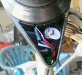
This was a new twist throttle, no extra features. I removed the little triangular plastic cover over the hall wiring pass through. First, a gob of white hot melt glue fell right off. Underneath, the black hall wire is in the middle of the other two. It had a piece of black shrink tube on it that had not been shrunk and had slid back downwire so that the bare hall wires were all side by side. The hall wires pass though an opening maybe 4mm square and the two outside ones were where they could and had been touching the middle ground wire. Moved and shrink covered the middle one up against the hall. Put a zip tie on the inside so the cable could not be pulled out of the housing. It works like it should have ten days ago. :D :D I certainly know more about this setup and componentry now!
throttlehall.jpg The picture shows what I discovered. The black shrink tubing is where I pushed it back against the sensor before I shrunk it. It was down much lower on the insulation. The bare sensor leg going to the white wire is hidden behind the shrink tube. No shrink tube on either red or white. You can see the green zip tie I put on the bundle so the wire can't get pulled externally.
 
Wow!!! That is one cheap throttle setup. All those wires should be insulated. What you had is a bit of an odd-ball problem, although not unheard-of. I was having similar dropouts last year and then my bike wouldn't run unless I went WOT. So I got a cheap replacement throttle that I have used for about a year. It is giving me the beginnings of the same problem, or it may be that the cutout switch built into my right hand break switch is a bit faulty.....maintenance on e-bikes is never ending. I have replaced the Hall sensor in my old throttle and it is ready to go in any case.

With what you described, those symptoms are generally related to lvc in the battery pack. That is why we pointed you in the direction we did, especially when you wondered why 43.8v was important on a 36v LiFePO4 pack. But it is all a process of elimination. And once we got you through the battery testing process then you knew it was something else.
But the process usually starts out with this kind of route: Are all the connections good? Does the charger work? Is the BMS working? (charging and balancing). Are the batteries themselves balanced? After that one can get into other parts of the bike for diagnosis. So we all learn as we go.

Also, on the downside, you cut your controller shunt prematurely, on the up side, you now get to find out how to repair a shunt and maybe upgrade to add amperage to your motor.
http://endless-sphere.com/forums/viewtopic.php?f=2&t=29097 :twisted:

Glad it is working anyway.

BTW, what are the voltages of your batteries when they are fully charged and balanced? Are they within .02v of each other?

:D
 
e-beach and friends, yes the cell voltages are tight as described. Not getting to total 43.8V, more like 43.2V. It could easily be the charger, even though rated to do 44.0V. This one is 2 amps. Recommendations for a better replacement?

Not sure if we want to repair the shunt, but may after further testing. It pulled me around on pavement for 3 hours doing top end, acceleration runs, consistently high speed and some decent paved hills. Typically, he runs it less than 10 mph. Would more amps help pull hills without slowing down as much? For his typical trips and in light of how long it lasted for me - he has plenty of battery reserve now when fully charged.

This has been fun in between frustrations, and I'm sure this is just the beginning! :D :D
 
Back
Top