SoCalbiking said:
Yeah it was a lot of damage :lol: should definitely just get a new 60° Board with matching hall sensors,
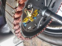
You can also just glue the sensors into their slots and handwire them...thats actually a much more common way these are built than using boards to hold them. It's just less easily repairable.
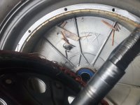
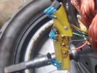
I basically clamped it together, used plastic epoxy and then made the broken solder connections.
If the connections were made using jumper wires across the broken traces, rahter than just solder bridging the breaks, it's probably a good enough repair. If solder bridges, though, that can result in cracks inside the bridge or at one or the toher of the traces, which can create a high resistance, and interfere with circuit operation--sometimes only under certain conditions...but inside a motor there is a lot of electrical noise being thrown around and a higher resistance will tend to pick up more of this noise than a lower one. The noise then interferes with teh signals that should be there....
You can test the sensors to see if they are working, basically, while the motor is open, by passing a magnet over each one (with the ocntroller plugged into the motor and the scooter turned on), and using a voltmeter set ot 20vdc range on each signal wire (red lead) and ground (blakc lead).
One reason I brougth up the possibliyt of it being the wrong kind of sensor before is taht there are two ways a sensor may operate--it may turn on only while magnet is near and then off when removed, or it may *latch* once magnet is near enough and stay in that state until hte opposite magnetic polarity passes it and then switch to the other state. If the sensors that came in the motor were of one type, but the one repalcing the broken sensor is the other type, the ocntroler may not be designed to interpret this correctly.
I was gonna add some bamboo I had but wasn't sure if the wood in the motor is treated to be fire resistant or something.
I doubt it.
")
Yes the middle hall is flipped I noticed that lol. Guess it came from the factory that way and it seemed to work fine so I kept it that way.
That's the design--60 degree sensors are done that way. (120 sensors usualy have them all facing the same way, and may be spread farther apart (more stator teeth between them; depends on how the motor is wound).
If you flip that sensor it reads and outputs differently and the controller then wont' understand the signals,
- I shall take it apart again to inspect it and tighten the fitment using bamboo shim on the middle flipped hall and see what happens. Controller seems to function fine as far as I can tell
But if you get improper motor operation, the controller isn't functioning fine, in that it isn't driving the motor correctly. Whether that is caused by the motor itself, the cabling from one to the other, or the controller, is what you have to find out.
Because proper controller operation requires proper feedback from the motor, then unless you have a second identical Daymak (or at least motor wheel) that you can swap out and verify it all works correctly with this controller, you don't know if the controller is malfunctioning or not (and it's not that uncommon for various types of mechanical wiring failures (whcih this would be classifiable under) to directly cause damage to the controller that make it less than fully operational in one way or another.
(most motors are not 60 degree types, so the controller you have may not work with a different motor, if it is only meant for that type).
A stutter or unusual noise, etc., is often caused by a sensor signal issue...but it doesn't mean its' the sensors themselves (most often it isn't, but in this case its' more likely due to the physical damage to the sensors and board).