• Hello ES! We could use some help to get us past the finish line on building the new knowledgebase for the forum.
    Can you donate? Please see our fundraising page. Thank you!

Hall sensors testing shows all at a fixed number

vwrado

🔌 New-ish
Joined
Sep 1, 2024
Messages
37
Location
USA
I have been trying to figure out the hall sensor error that I got on a motor that shows hall sensor error on 3 different controllers. The motor is from a super 73 rx. I have disassembled the motor and used a multimeter to test all three sensors and two sensors yellow and green and shows a constant 4.98V while the blue shows constant 3.98 and doesn't change when I rotate the motor. I have sucessfully tested a hall before and can see that it usually switches near 0 and up to almost 5. So this is new to me. Is it possible that all hall sensors are bad? I thought it was a wiring short somewhere but couldnt find the short anywhere. Does anyone have any insight on if they think its all 3 sensors that are bad or am I looking in the wrong spot?

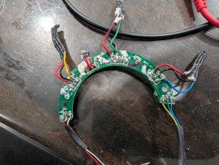
here is a picture of what I am looking atPXL_20250615_044053273.jpg
 
Are you testing hte sensors using a pullup resistor (5k-10kohm) to their supply voltage, on each signal line? If not, the signal won't be valid.

Or with the hall sensors plugged into a powered-on controller (the contorllers have these pullups built in).


If, with pullups in place, you have sensors that do not toggle between around 0v to around 5v as magnets pass them, the sensors have probably failed and would need to be replaced.

The usual reason for them to fail is motor cable damage that shorts phases to hall signals or hall power; this usually blows up both motor halls and controller internals. Or overheating of the motor.


For further info, there are many threads about testing hall sensors, replacing them, part numbers used, sources for the parts, etc., if you poke around. ;)
 
It seems like all the sensors are bad. That's pretty hard to do, usually they go one at a time. If the 5v supply line made contact with a phase wire, that would do it. Any recent crashes?
 
A lot of my testing is starting to not make sense to me. I have tested the following:

red and black wire on the hall sensor plug where the controller connector plugs into the motor (6 pin plug) I get 4.5v which seems normal
then red from the connector to the black wire on the motor where the pcb board is and get .24
then red from the connector to the red on the motor and I get a constant 4.5v
Black at the connector to the black at the motor - 4.23v
black at the connector to red on the motor - 0

Is this a short somewhere or a chip on the pcb burned?
 
A lot of my testing is starting to not make sense to me. I have tested the following:

red and black wire on the hall sensor plug where the controller connector plugs into the motor (6 pin plug) I get 4.5v which seems normal
then red from the connector to the black wire on the motor where the pcb board is and get .24
then red from the connector to the red on the motor and I get a constant 4.5v
Black at the connector to the black at the motor - 4.23v
black at the connector to red on the motor - 0

Is this a short somewhere or a chip on the pcb burned?
Sounds like a broken ground wire. You might want to turn all power off and measure the wire continuity for each wire from the motor to the controller.
 
So I have dug deep in and removed the hall sensor and board. Did a little testing to see if there is a short. Note that I am not experienced with electrical or any of this so this is all a learning point for me. Excuse my dumb questions.

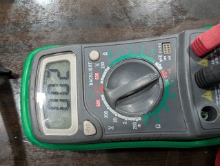
In my test all the colors shows low resistance in continuity which is about .01-.02. I tested red to red, black to black, blue to blue and etc.

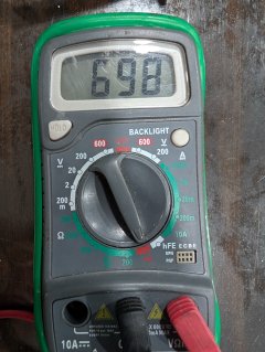
However when I tested black to yellow, blue, and green, I get around 700 for all three colors. What does that mean?

Black to red I get about 1250

Lastly, is there anything else I can check?

Attached are some pictures of what I got. The .02 is what I get when I test red to red, black to black etc.
The 698 - 700 is when I test black to blue, green or yellow.


PXL_20250620_040117182.jpgPXL_20250620_040104323.jpg

PXL_20250620_040029354.jpg
 
Testing that way doesn't really tell you useful info.

The best way you can test the sensors is by actually using them under the conditions they're normally used in (inside the motor), or simulating that with a manual magnet pass that changes the polarity of the field repeatedly (which is what happens in the motor), and seeing if the output grounds (turns on) or opens (turns off) and goes to supply voltage, when the sensors are powered the same way they would be in-use, and have a pullup resistor from each signal ilne to the supply voltage positive.


If you want to test for resistances between the wiring of different traces, you'd have to remove the sensors and any other components, because the components interfere with the readings you should get.

If you want to test resistance (continuity) of the actual wires and traces, from the controller-end of the wiring to the points on the board where the sensors are soldered in, you can do that with or without the parts in place.


Your previous test results indicated a broken ground wire (the negative of the 5v to all the sensors), somewhere between the controller internal PCB and the motor internal PCB.

If you do a continuity test of that wire, from inside the controller to inside the motor, with it all connnected but not powered on, what are your results?
 
Back
Top