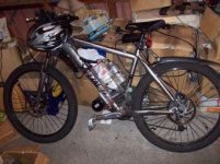
headline 300w on 57V update

In case anyone is interested I got the calculations wrong for the number of Km's on the gearbox :oops: I had missed one of the 5's. lack of sleep I guess...

should be:
52 weeks * 5 days * 5Km * 2Years
Giving approx 2600Km on the planetary at stock power (300W) on internal 24V controller with no obvious damage.
I would say the motor has done at least that as I've had it more like 2 1/2 years as It gets used a bit on weekends too.
 
Looks like the controller I ordered from e-carzyman should be here in the next day or so.
Tracking shows its in NZ as of lunch time so probably in Auckland.
If its trip through customs is speedy It may be in Napier tomorrow :D.
I'm not expecting any duty or delays because its below our rather generous limits.
This means I should be able to get this bike up and running again by the weekend with More Power :lol:.
I may try and keep the motor current down to slightly above stock but allow higher RPM to see if i can preserve the planet gears for a while.
Since its through the gears on the bike I get more effective output power without increasing the torque on the gearbox by just increasing RPMs and gearing down with the bikes gears.

[pre] Try that with a frock motor :p [/pre]
It may mean I can assist less at higher RPM's but at warp speed whats the point in assist!
I know looking the part and teasing lycras!
Damn hard to keep an even cadence and look real with no back pressure from the pedals!


Edit:
I've started hacking up the control board but out of curiosity I looked up the MOSFETS it used
IRF3205
VDSS = 55V
RDS(on) = 8mR
ID=110A
Not a bad MOSFET for the original application( 300W) where I saw peak currents over 25A on the battery input ( probably the reason it killed the original lifepo4 battery).
 
Parts are in :D

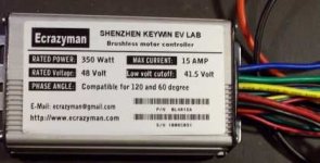
One 6-FET ECrazyman 6 FET controller
New full twist throttle (Chinese one).
New hall sensors in case the originals are cooked
Some IRFP4110s

6-fet-small-100_2804.JPG

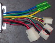
connectors1-circle.JPG
Not that I'm too worried as I will open it up but just curious does anyone know what the circled 3-pin (red/green/black wires) black connector is for?

I plan to get things going with the controller stock as there is enough variables in making sure the motor anbd halls are setup right.
Then I will probably swap out the MOSFETS.

I need to make a high-res scan of the label on my flat bed scanner before I remove it from the controller so that it can be edited for regulatory compliance :wink: :wink:
It will avoid having to compensate for slight camera angles issues when creating a new one.

I will use the throttle so I don't have to piss with bypassing the slow ramp in the headline throttle.
I have only brought a cheep throttle for this project but for my high power project I will probably use a magura throttle .
As for reported problems with the headline throttles, I had no issues with it apart from the strange / stupid stepped ramp up of the throttle output.
 
Ricky_nz said:
.............Not that I'm too worried as I will open it up but just curious does anyone know what the circled 3-pin (red/green/black wires) black connector is for?


Pedal motion sensor (Pedelec). I've just upgraded my 116 6 FET controller thanks to the advise from Jeremy. I went with IRFB3077 FETs, I won't be using more than 48v, and I also upgraded the phase and input caps to Panasonic NHG. These are a higher voltage rating (originals where 50v) and low ESR types.
 
NRG said:
Pedal motion sensor (Pedelec). I've just upgraded my 116 6 FET controller thanks to the advise from Jeremy. I went with IRFB3077 FETs, I won't be using more than 48v, and I also upgraded the phase and input caps to Panasonic NHG. These are a higher voltage rating (originals where 50v) and low ESR types.
Thanks,
Ok so that wire won't be needed then. Its the only connector not listed on ecrazymans ebay page.
I will initially be running 14s LiPo as thats what I have currently but might play with more Volts later.
Early next week I will be ordering some nice capacitors and other parts for my high power controller, I'll just make sure I order extra caps since I'm populating my high power controller for 100V operation. Also and any caps that are ok for the 7+KW drive will surly handle this little 6Fet even with better MOSFETS :lol:

I'm resisting my normal urge to rip open a device containing electronics before I use it because I want to make sure I have the motor wired correctly first then all bets are off :).

Just found a use for old DB9 serial cables that I had around with no purpose.
One was a fairly thin black one so its just been cut up for the black multi core wire to use for the halls.
 
The motor is wired up.

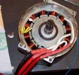
I have 3 10AWG wires leaving the motor + 1 multi-core cable containing
3 hall signals, +V, 0V, 2KR NTC, internal thermal switch?.

The phase wires are different offcuts and one isn't silicon either, I would have preferred 3 the same colour or 3 different coloured ones.
I must remember to buy more on my next order from hobby king.
These wires are overkill, especially when compared to the windings in the motor.

The internal thermal switch? reads <1R at present so I assume it is a bi-metallic switch of some sort.

I had to do some butchery of the PCB because it was not obvious exactly where the hall power went on the board. I removed the smoked IC and the current at 5V on the hall sensors dropped to below 10mA so I call it done. Not sure how many volts the controller puts out on the halls. I will definitely measure this and check there is no voltage dependant loads accidentally left on the PCB. To be honest there isn't much left in the way of semiconductors once the main chip is removed just a voltage reg and one small other chip. I removed the MOSFETS to make more room although I probably didn't need to.

I had to cut a chunk of the PCB away where the cables exit the motor to make room for the 3 phase wires. Big side cutters to the rescue :twisted:

I've checked with an LED that all 3 hall sensors toggle when when the shaft is rotated.

Sorry no flames tonight. its nearly 1 in the morning here and I know better than to power things like this up this late.
Be sides I have work in the morning so I guess I better get to bed shortly. Damn work interfering with play.

I still have to sort out the hall sensor phasing etc.

phases-100_2811.JPG
wires for external controllerl.JPG
 
It runs! :D

Now I need to figure out the best hall combination.
so far I have found one smooth clockwise that trips the 2.5A current limit of my supply very early and one anti-clockwise that runs faster and smooth before hitting the current limit but starts bumping up against the current limit at mid throttle.

I have only tested with one combination or phases and 3 hall combinations so far so still a bit to go

There must be a short cut to this. I know the order of the hall sensors around the motor but not sure how that relates to the little 6FET ecrazyman
I'm not sure if 2.5A no load (without planarity gearbox) is too high for this motor running on 48V or not.

I think I read somewhere on the forum that these motors are advanced a bit so maybe that accounts for the speed difference.


Edit:
I have just swapped one pair of phases and have now found a fast and relatively low current in the clockwise direction I need.
I guess I need to check a few more combinations to be sure.
The fast clockwise is just hitting the current limit on my one of PSUs so maybe its ok.
I'm running 2 x 0-30V psus in series to get 48V and with both current limits at max the first one limits a little early at 2.4A and since that goes into I limit at full throttle only I figure the combo is probably ok.

Had anyone else run the 300W headline on and external 48V controller and got any typical no load currents. I'm lazy and don't weant to wast time checking all 36 combinations of which I'm sure there is a lot of overlap.

Its a bit hard to test thoroughly since I hit full current limit on the supplies.
Just played around a bit more and the combination I have now is 2.1A once it stabilises at full throttle, it bounces into current limit at 2.4A briefly during acceleration as I would expect extra power needed for accelerating before settling done.

Maybe I should break out the scope and measure the RPM from a hall signal or look for abnormal waveforms on the motor.

Just measured a Hall signal at 411Hz, full throttle.
Not sure how many poles etc this motor has so it doesn't help much though.

Edit:
I have lost some of the grease. These gearboxes as messy when open. grease on hands, bench, cat, etc :lol: so I want to top it up a bit (It has also run for over 2600Km).
Would normal automotive grease be ok in this application?
Can I just add grease to the existing grease or should I flush out the olde grease with a solvent?

I guess I should start tidying up the wiring so I can take it for a test ride tomorrow after I sort the grease situation before I mod the controller etc.
 
Had my PSU set a little low in volts. Just did a couple more tests with a more realistic voltage.

460Hz at 50V
526Hz at 57.2V
The PSUs had just started hitting curent limit at 57V. I guess the fact that the RPM is probably more than twice that with the original controller has something to do with that.

The motor is really screaming now! :D can't wait to get it on the bike with 14S lipo!

I guess having 57V even if I limit the power to 300W should be quite good for widening the time between gear changes due to the extra rev range of the motor now but I guess it will have messwed up my ability to assist the motor at max RPM.


Whats the max input voltage of these 6 FET e-crazyman 48V controllers without modification? I know its running at 57.4V no load but I want to know its safe for a test ride before I change the FETS etc?
 
I've just uploaded a video of a bench test of the motor.
At low RPM I can feel a vibration but Its hard to tell if this is any more than I felt with the origional controller because I only ever4 ran the motor with the internal controller while it was bolted firmly to the bike. I hope I got the halls right. Guess I should go easy for the first ride and watch the amps etc.

Not shown in the video is install and testing of the NTC.
After soldering the sleeving the wires to the NTC I tacked the sleeving to the windings with a small blob of hot melt glue and put some thermal paste between the glass bead and the winding. I then used small a piece of need-it ( less messy and quicker than mixing up epoxy) to hold the sleeved legs/solder joint to the side of the winding form in such a way as the glass bead is firmly against the stator windings. I won't remove the hot melt that was only used to hold things in place until the need-it set as I didn't think a small blob of hot melt will cause any problems even if it fully melts. I purposely kept the need-it away from the winding as I don't want to do anything that could make a rewind difficult.
Anyway the NTC worked well, it tracks the temperature quite quickly. I converted the resistance back to temperatures using a table from epcos and its all believable.

[youtube]JBqZ3U3U0Oc[/youtube]
 
Nicely done!
 
'I have lost some of the grease. These gearboxes as messy when open. grease on hands, bench, cat, etc :lol: so I want to top it up a bit (It has also run for over 2600Km).
Would normal automotive grease be ok in this application?
Can I just add grease to the existing grease or should I flush out the olde grease with a solvent?'

hi Ricky; I did what Bertie did with his gearbox and added atf (Dexron I think it is-its red anyway) to the existing grease to allow it to 'move' around more especially when warm. Mine was pretty thick originally and wound stick to the outside of the case meaning no lubrication to the gears....it is now much better (crosses fingers) I run a 48v 1200w set up and have 600 miles on it with no gear wear as yet..but am 'smooth' on the throttle :lol: . I contacted Lyen a while ago to get some gears cut but apprently his machinist was not able to produce them for some reason. :(

Ian :D
 
Dingo2024 said:
hi Ricky; I did what Bertie did with his gearbox and added atf (Dexron I think it is-its red anyway) to the existing grease to allow it to 'move' around more especially when warm. Mine was pretty thick originally and wound stick to the outside of the case meaning no lubrication to the gears....it is now much better (crosses fingers) I run a 48v 1200w set up and have 600 miles on it with no gear wear as yet..but am 'smooth' on the throttle :lol: . I contacted Lyen a whilw ago to get some gears cut but apprently his machinist was not able to produce them for some reason. :(
Thanks Ian,
Its good to know you are having success with keeping the gears in good condition :).
I'll see if one of my mechanic mates has a little spare ATF. I noticed in my motor that most the original grease was on the sides of the gears and not on the teeth and on the sides of the case with very little on the ring gear so it sounds similar to what you say yours was like.
ATF or some form of oil does sound better though especially with the higher speeds that the motor now revs to.

I haven't modded this controller yet, its at stock 350W so only a little bit more power than the old internal 300W one but once I'm happy with it then I'll swap the MOSFETS and tweek the shunt to get more power.

I'm a little concerned at present if I go wide open throttle on the bench It gets quite warm within a minute (no airflow like it gets on a bike) I might keep working through the hall/phase combinations to see if I can find a lower no load current combination although it seems to be running pretty smooth.
 
Hi,

Just got back from a quick test drive held together by tape :lol:
I need to tidy it up a bit and then maybe to a test with video.

I did get the motor quite hot but then today is hot. It was working to the point the 6FET felt quite warm too. My turnigy meter said 25A peak and 1100W peak. seems a little high for an unmodified 15A controller. maybe I better find a way to calibrate my turnigy meter or confirm its accuracy..
The same turnigy meter said the original internal controller was drawing 750W peak.

It did feel a bit more powerful, the power band feels wider than the internal controller.
If I'm in a gear thats too high to start the controller cuts out very quick. I assume this is normal protection as the internal controller did something similar only a bit slower and after a couple of attempts to move (pulses).

I haven't done a speed run yet, just stayed around home so max about 38Kph before I run out of room.
I think I might need to do something about the initial throttle response as with this throttle/controller combo it is instant and I can hear things getting abused if i'm too quick. just needs a small ramp over a fraction of a second rather then the very slow steps of the original throttle.

the gearbox is noticable quieter than before so I guess after 2600Km on the internal controller it had all migrated away from where it needed to be. moving it back seems to have helpede byt I will look into improving the situation with either ATF or more grease or both.

There is still a possibility the halls aren't right as I'm still running on the first combination that run smooth in the correct direction.


edit:
Here is a video of the first runup of the motor/controller on lipo that I did before bolting it back onto the bike for the test ride.
I have updated the video link to one where you can read some of the numbers on the meter. Still not perfect but better.
[youtube]AOdUGn-dXyE[/youtube]

Ricky
 
Test Ride 2

This one was longer and burnt off 3.5AH, I forget to take note of the Kms.
I got the motor hot but didn't get to take a temp reading because I had to deal with my cat, in the time I was gone, not long she had caught a bird :roll: and brought it in through the cat door and into my computer room at the other end of the house.
She has only had the cat door for about a month and this is the first prey she has brought in through it. Usually it was through open doors etc.

I had intended to do a video but I forgot to clear out the card first and with a minor issue not long after starting i ran out of flash.
The issue was one of temporary installation as I still want to open up the controller. I had the controller taped to the frame in airflow and just dropped the batteries in the panniers one per side but the series cable was a little short and popped off when I dropped off a curb.. Also my temporary connection to the ecrazyman power connector with push on terminals had a lose contact due to reusing a wire/crimp from the old install. This will be removed for final install. I'm thinking of beefing up the controller so it will get bigger power wires anyway.

With the ecrazyman at 350W the bike seems to have just slightly better performance than stock 300W on the internal controller. You can go a lot longer in one gear now, The extra RPMS help here. I got to 30Kph in 1st. This bike has 8 gears. the front derailer is removed and I run a 44t at the front and 11 - 32? at the back.
In the lower gears once you get moving pedal assist isn't practical any more but as the 350W runs out of steam at higher speed you can choose a gear that allows you to assist the motor well. I hit 50Kph while assisting the motor and it was just a little bit easier than doing that on the original 300W elation kit.
Cruses nicely at around 35Kph without help.
The throttle response is much better than the stupid stepped response of the original one. I just need to get more accustomed to not slamming it on hard and waiting for things to happen.

I will put some charge back in the batteries and might do a night run later with video.
 
Test Ride 3
I did a night ride but as expected the key-chain camera doesn't do well in low light.
I found half way through I had to move the LED lights up to look further down the road as I ramped the speed up. This is a real problem with LED lights. I could have set one down and one up but I prefer 2 down the road. I really need to get some really high power ones rather than these two 3W LEDs. The law here says upto 2 lights so I guess I need to go bigger :twisted:

After burning about 2.6Ah the motor winding temp was about 87 degC. This was measured about 1 minute after getting back (had to grab meter).
That explains the quite hot case on the motor.
Still sounds quieter than it did on the internal controller. I'm convinced that the lubrication wasn't ideal for some time while running at 300W but I need to improve it as I'm sure the grease I moved around will migrate away from where its needed again.

I think I need a bit of time to get use to when to shift with this combination.

NTC temperature measurment:
Small glass bead NTC ideal for sticking in/on your motor windings. I have added this to my headline 300W and I will add one to each of my turnigy 80-100 when I pull them apart.
RT is the resistance of the sensor
eg 1000 / 2000 = 0.5 -> just under 45 deg C

[pre]NTC Info for EPCOS B57550G202J RS # 484-0127
This table is based on EPCOS data but with only the values for this NTC.
You can use this table to quickly convert a resistance to a temperature.
R25 = 2000R
Number 8401 B0/100 = 3390 For 2K NTC
T (°C) RT/R25 a (%/K)
– 55,0 48237 6,2
– 50,0 35488 6,0
– 45,0 26390 5,8
– 40,0 19825 5,6
– 35,0 15037 5,4
– 30,0 11511 5,3
– 25,0 8,8893 5,1
– 20,0 6,9218 4,9
– 15,0 5,4326 4,8
– 10,0 4,2961 4,6
– 5,0 3,4220 4,5
– 0,0 2,7445 4,3
5,0 2,2158 4,2
10,0 1,8002 4,1
15,0 1,4714 4,0
20,0 1,2097 3,9
25,0 1,0000 3,8
30,0 0,83110 3,6
35,0 0,69427 3,5
40,0 0,58282 3,5
45,0 0,49158 3,4
50,0 0,41652 3,3
55,0 0,35446 3,2
60,0 0,30292 3,1
65,0 0,25994 3,0
70,0 0,22392 2,9
75,0 0,19363 2,9
80,0 0,16805 2,8
85,0 0,14636 2,7
90,0 0,12790 2,7
95,0 0,11214 2,6
100,0 0,098635 2,5
105,0 0,087023 2,5
110,0 0,077007 2,4
115,0 0,068340 2,4
120,0 0,060818 2,3
125,0 0,054270 2,3
130,0 0,048554 2,2
135,0 0,043551 2,2
140,0 0,039159 2,1
145,0 0,035294 2,1
150,0 0,031885 2,0
155,0 0,028870 2,0
160,0 0,026197 1,9
165,0 0,023822 1,9
170,0 0,021707 1,8
175,0 0,019820 1,8
180,0 0,018132 1,8
185,0 0,016619 1,7
190,0 0,015260 1,7
195,0 0,014038 1,7
200,0 0,012936 1,6
205,0 0,011941 1,6
210,0 0,011041 1,6
215,0 0,010225 1,5
220,0 0,0094848 1,5
225,0 0,0088113 1,5
230,0 0,0081978 1,4
235,0 0,0076382 1,4
240,0 0,0071268 1,4
245,0 0,0066590 1,3
250,0 0,0062302 1,3
255,0 0,0058368 1,3
260,0 0,0054753 1,3
265,0 0,0051426 1,2
270,0 0,0048360 1,2
275,0 0,0045532 1,2
280,0 0,0042920 1,2
285,0 0,0040504 1,1
290,0 0,0038266 1,1
295,0 0,0036192 1,1
300,0 0,0034267 1,1[/pre]

 
hi Ricky,

good to see you are making progress and the gearbox is quieter :wink:

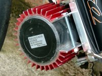
here is my 'belt and braces' approach to heating issues on the motor...although not sure if you have enough space to run this

it has definately worked for me...no more thermal cutout :lol:

Ian :D
 

Attachments

  • DSCF0007.JPG
    DSCF0007.JPG
    69.7 KB · Views: 2,204
Dingo2024 said:
hi Ricky,
here is my 'belt and braces' approach to heating issues on the motor...although not sure if you have enough space to run this
it has definately worked for me...no more thermal cutout :lol:
Ian :D

Thanks Ian,
That looks really good, better than the glue on ones I saw on the cyclone site.
I'll have to get hold of one of those, I guess supercheep etc would have them.
The motor basically hangs below the frame so it should be possible.
Here is a an old photo of the bike with the elation parts on it.
How was the radius compared to the original radius of the cooler? I guess it must be quite close as it looks like you got a good fit.

I haven't hooked up the overheat sensor yet. It would probably be a good to do so though. I have got the NTC I added in there also but I don't have a monitor for it yet. Maybe it would be better just to rig an alarm circuit to the NTC so I don't get sudden loss of power at a dangerous moment.

old photo with origional elation parts small.JPG


EDIT:
One very dark test ride. It wasen't that dark really. These little keychain cameras have their limitations :lol:
[youtube]VaqRtoHlSn0[/youtube]
When I compare this with a test ride with the internal controller I confirmed that I have noticeably less gear changes with the higher system voltage.
 
Ricky_nz said:
Dingo2024 said:
hi Ricky,
here is my 'belt and braces' approach to heating issues on the motor...although not sure if you have enough space to run this
it has definately worked for me...no more thermal cutout :lol:
Ian :D

Thanks Ian,
That looks really good, better than the glue on ones I saw on the cyclone site.
I'll have to get hold of one of those, I guess supercheep etc would have them.
The motor basically hangs below the frame so it should be possible.
Here is a an old photo of the bike with the elation parts on it.
How was the radius compared to the original radius of the cooler? I guess it must be quite close as it looks like you got a good fit.

I haven't hooked up the overheat sensor yet. It would probably be a good to do so though. I have got the NTC I added in there also but I don't have a monitor for it yet. Maybe it would be better just to rig an alarm circuit to the NTC so I don't get sudden loss of power at a dangerous moment.


EDIT:
One very dark test ride. It wasen't that dark really. These little keychain cameras have their limitations :lol:
[youtube]VaqRtoHlSn0[/youtube]
When I compare this with a test ride with the internal controller I confirmed that I have noticeably less gear changes with the higher system voltage.

hi Ricky,

here is what it looks like before fitting

http://cgi.ebay.co.uk/FOLIATEC-RED-ANODISED-ALUMINIUM-OIL-FILTER-COOLER-COVER-/230402052782?pt=UK_CarsParts_Vehicles_CarParts_SM&hash=item35a50852ae

the 1 I got was 74mm dia and my motor is about 84mm dia so not much difference, used a rubber hammer to tap it on and artic silver thermal compound under it. It needs to be cut down in width and this is a pain (or was for me :roll: ) with a hacksaw....but it has done the job

Ian :D
 
Hi Ricky, a question to you sir.........I too currently have problems with the step on the factory headline throttle operation. Do you think this is caused by just the throttle (design) or a combination of throttle / controller. My options are to run a pot on the stock throttle to improve range and smoothness, run the stock throttle through the CA to become a current based throttle or replace the stock throttle with a magura and run that through the CA...all with the stock controller.......any comments or thoughts. Its just too twichy at the moment........and that is unmoddified :roll:

Ian :D
 
HI Ian,
Dingo2024 said:
Hi Ricky, a question to you sir.........I too currently have problems with the step on the factory headline throttle operation. Do you think this is caused by just the throttle (design) or a combination of throttle / controller. My options are to run a pot on the stock throttle to improve range and smoothness, run the stock throttle through the CA to become a current based throttle or replace the stock throttle with a magura and run that through the CA...all with the stock controller.......any comments or thoughts. Its just too twichy at the moment........and that is unmoddified :roll:
Ian :D

The origional headline throttle seems to have a microprocessor in it and I think the stepped ramp is intentional, just stupid :roll: . I was going to open it up and try and bypass it but never got round to it. It should be possible to connect the hall sensor directly to the output wire rather than going through the micro.
I had for a test hooked a pot up directly to the internal controller ( before my accidental reverse polarity incident :oops: ) and the response was instant like the new external controller and normal throttle.

I don't own a CA so I can't comment on using one.

Now I need to find a nice way to take the edge off the new setup :) from one extreem to the other :lol:

I'm not sure if the controller I'm using can be configured to add a quick ramp rather than instant but if not I think I could put a small RC filter inline to slow it down just a tad to try and protect the drive train.

A small RC filter may meet your needs with the factory controller too. I wouldn't think it would take much. Maybe ramp to full over 1/2 second. Would probably want to add a diode so that the ramp becomes asymetric so the throttle ramps down quicker.

I might try and find time on the weekend to have a play. I need to get the circuit board for my high power controller checked and ordered first though.

I think I saw some discussions about this a while back but haven't gone looking yet.
 
Update after riding the bike with the unmodified external controller @ 57V to work for most of a week.


The extra RPMs are really useful, significantly reducing the number of gear shifts required. I can now get from zero to 38Kph in 2 gear shifts without pedaling :D. It does impact on being able to assist as the front crank now spins faster.

The cheep chinese throttle needs some dampening and/or maybe the electrical slowing down discussed above.
This throttle causes the motor speed to vary when you go over a minor pothole as it is too easy to move. I will definitly be using a high quality throttle on my 7KW bike project. :lol:

My chainline isn't perfect in the lower gears. This is caused by having to have the 44t sprocket cleear the frame. Since I have no front derailer any more I might need to put a nylon block or similar to prevent the chain jumping off the inside of 44t from sprocket in the low gears. I suspect this problem is worse with this controller / throttle combination due to rapid torque fluctuations.
 
Just an quick update.
I am really liking this 350W controller with 48V and quick throttle response although having the motor speed very every time a bump jars your wrist is a bit strange. ( only a problem when trying to crawl along <20KPh).

This bike is a bit of an animal for such low power now. A few times I have been in its lowest gear 44 - 32 and pedalled as I take off (as was necessary before) and next thing the front wheel is in the air :lol: (I'm not complaining).
I'm sure this can't be good for the planetary gears. I should open it up and have a check soon.

I guess Its good practice the high power bike I'm building.

In summary this is a great upgrade for a 24V elation kit! 48V Rocks!

It does 30KPh in the lowest gear given long enough thanks to the extra RPMs
 
Update after 350Km's
Still working :D.

I thought the sound of the motor/gearbox had changed and got worried about the gears so I pulled it apart.
The teeth still looked ok so running at 350W with much higher RPMs seemed to have heped preserved them but again the grease had all moved away leaving minimal lub and allowing greater noise. This is the same condition I found the moter when I first pulled it apart.
gears_after_350Km_100_3089_small.JPG
This time I have added a little more grease with some left over lawn mower oill and I will see how it goes.
There is definitely too much loss if you put way too much grease in the gearbox but grease with some oil seems to run smoothly and quietly. I will probably pull it apart after I have a few hundred more kilometers on it to check again.

Other issues with the bike:
My change to SBP freewheel etc is working but my chainline is a bit bad in low gears and I have thrown the chain a few too many times shifting from the lowest gear. The only real use for the 32t at the back is for fun although you can get to 30Kph in that gear. I have removed one of the smaller sprockets from the middle of the cluster and put it next to the hub as a spacer. allowing my to use the 32t and 6 other gears while the 8th is an in between ratio that is not needed with motor power. The chain line is still a bit bad on the 32 so I might move one more sprocket behind it. so far riding the bike it seems to shift fine over the missing sprocket :D .
I need to find a way to limit the derailer as the Low setting screw is right in and it can still try and shift past the 32T. I guess altering the cable length so the control can't get there might help.

I also finally replaced my hayes hfx 9 back brake after the last pads wore out. The post that holds the pad had come free from one of the pistons. I had pushed it back in at the previous pad change but it come loose again as the pad wore and I decided enough was enough, I didn't want to try and glue it back and given the need to buy not just a caliper repair kit or half caliper but a bleed kit I decided to cut my losses and buy an avid 203mm elixer R from chain reaction cycles, I actually brought 2 since my 7Kw bike I'm building has an elixer on the front and now I have decided to put one on the back I ordered one for that too. They have the rear 203mm one on special :D approx 128NZeach + 10 shipping (http://www.chainreactioncycles.com/Models.aspx?ModelID=29728) and its a much better brake, much more controllable than the hayes :D.
You really need that control when trying to bed in the pads on the rear with hookworms.
I found with the hayes it was all too easy to lock the rear with 203mm disc but the avid seems to have much better modulation.
I should probably buy an Avid bleed kit at some point now I have 3 of them.

As for the throttle I haven't got round to doing anything with it. I think most the issue is just that its voltage control not torque so I will probably do a 6 fet version of my vector controller for this bike at some point once I have it working on the higher powered bikes. That will give me a true torque control throttle.
 
I was doing some maintenance on my bike and remembered its been a while since I converted it to external controller and run it off 14s2p (57.4V) so thought i would do an update.
(Forced maintenance due to worn brake pads Elixer R's down to the metal clip.)

Looking back its been 10 months already :shock:.
I'm still running the 350W ecrazyman unmodified. I have measured significantly more power in than that.
I haven't had any problems with the planetary gears.
Still using grease with a splash of oil but I really want to try sealing it up and running proper gear oil.
I think I saw a while ago someone on here tried sealing one up.

Definitely like the wider rev range. I haven't had time to add additional cooling to the motor.. after 2.5Km run to work it is warm so hasn't worried me much.

I'm trying to keep this bike reasonably reliable as my daily ride while i focus on my other projects. The kitchen should be out the way in a few weeks time.
So far the only issues I had were the motor mount slipping down the frame and the chain getting lose. put a 90 degree twist in the chain when it came off once :lol:

I am still running the SBP freewheel from when i converted this bike to use one and it does have a little side play but not much more than when I first installed it.

The batteries are my original turnigy ones which are over 18 month old for the newest cells ( I damaged a couple of the originals with a minor over discharge early on and replaced a couple of puffy cells at that point. The oldest cells are 21 months old...
 
Back
Top