Headline Motor & Cycle Analyst with limit functions

AusEbiker

100 µW
Joined
May 15, 2010
Messages
8
Hi all – I need a bit of advice from some of the 'been there – done that' types please.

I have purchased a used e-bike kit similar to a Cyclone kit. It uses a 200 Watt Headline Motor (with an internal controller) and an Oro brand throttle.

I am currently planning the installation of this system to a flat bar road bike. I have purchased a Cycle Analyst (version 2.2) and wish to connect the CA's limiting functions. I also have some reed switches to function as brake cut out switches. My objective is to simplify and minimise the amount of wiring on the bike.

I have prepared two diagrams – one being the kit as purchased, and the other being the planned installation. I need some input to verify my proposed circuits.

In particular, I am confused about the ground connections and whether it is ok to connect ground wires (24V & 5V) together at various locations.
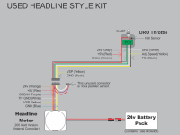
Wiring Schematic - AusEbiker as purchased.png

Wiring Schematic - AusEbiker Planned.png

I intend to post updated diagrams as feedback is given, and hope that these might help others in the future.
 
As a rule of thumb, any grounds that used to be connected before probably still have to be (or at least, can be). Any that weren't, shouldn't.

For some reason I can't download or view the images, so i don' know exactly what you've got or are planning. :(
 
here the photo..
 

Attachments

  • Wiring Schematic - AusEbiker as purchased.jpg
    Wiring Schematic - AusEbiker as purchased.jpg
    31 KB · Views: 1,969
Thank you Kentlim for posting the jpg versions.
I was just trying to resubmit them and you have saved me some effort.

And thank you for your reply Amberwolf. I understand that, as you say;
"any grounds that used to be connected before probably still have to be".

I guess I am wondering if it is OK to connect them to different points in the
overall circuit.

As you should now be able to see in my 'Planned Installation' diagram - I want to
use the 5V pad and the nearest ground pad on the CA board to power the Hall
effect throttle. The throttle (Hall sensor) output signal would be connected to
the Vi pad on the Cycle Analyst. The Th pad on the CA would be connected to
the VSP (Yellow) wire on the Headline controller.

This means that I would be capping off the following wires from the Headline
(internal) controller;
24V (Gray) - previously used by Oro throttle for LED battery display = not required
5V (Red) - previously used to power Oro PCB and Hall sensor = not required
GND (White) - previously used for Oro PCB and Hall sensor = not required

- I want to know if this is OK.

Brake Switches
I also want to connect some brake cut out switches and I have some NO/NC
reed switches for this purpose.

Am I correct in assuming that the BREAK (Purple) wire from the Headline
controller is a 5V signal that activates, by being connected to ground,
(and kills the motor) when you apply the brake/s?

This is what I have assumed. As you can see in my diagram - I have
connected one side of the reed switches to the BREAK (Purple) wire and
the other to the GND (Blue) wire.

The reed switches would therefore be connected to the normally closed
(NC) contacts.

The switches would be held open by magnets when the brake
levers are not touched. The circuit would be open and the motor
would operate.

When the levers are activated the magnets move away from the
reed switch and the circuit is closed, killing the motor.

- Is this right?


The first diagram should be titled 'Used Cyclone Style Kit' by the way.
 
You can *probably* use the CA ground instead of the ground coming off of the motor. I do that on my bike for the same reason, to reduce the number of wires needed from the handlebars to the controller. But it does depend on how the 5V power supply in the motor is designed. If it was isolated or positive-grounded or something, then it wouldn't work.

In order to determine for sure whether you can substitute the CA ground for the white ground wire coming from the controller, you can perform a couple of simple tests to confirm your assumptions.

Assumption #1: The battery negative (-) is the same as the CA ground
Test: use a meter in Ohms/resistance/continuity-test mode on the CA ground pad and the black anderson connector on the shunt. If those two leads are connected internally, that means the CA ground is the same as battery negative. Actually I know this is true on my CA, but it's a slightly different model than yours so you should check anyhow.

Assumption #2: The battery negative (-) is also the same as the motor/controller ground.
Test: same test (connectivity), this time between the negative power connection to the motor and the white ground wire coming out of the motor. If they are connected, white is also the same as battery ground.

If both of these things are true, you can use the ground on the CA interchangeably with the ground on the motor/controller (at least for small currents).
 
Thanks for the input Stingray17.

Because the kit is in pieces at this stage, and because I plan to replace the Oro brand throttle, my focus is now on the wiring of the Headline controller.

I have prepared and attached a new diagram, showing the wiring for a 200W headline motor. I would appreciate it if someone can confirm this diagram please.

In my first diagrams I have incorrectly labelled the blue wire as a ground wire. As you can see in the diagram, I now believe that it is not used.

The white wire therefore seems to be a common ground.

I can list my sources if needed - but I am pretty certain this diagram is correct. It would be great to have some confirmation however.
 

Attachments

  • 200W Headline Motor wiring.jpg
    200W Headline Motor wiring.jpg
    27.8 KB · Views: 1,922
Well, you can verify that white is a "common" ground by using a multimeter as described to confirm that the white wire is internally connected to the black battery terminal wire (typical negative ground setup). In other words battery negative (-) is the same as ground. To be honest, I wouldn't trust any other method - even if you have good sources, it's still possible that they changed wire colors from one revision of the motor to another.

Similarly, you can verify that orange is the supply voltage wire by checking whether the orange wire is internally connected to the red battery terminal wire.

Then, you can hook the battery up to power on the controller, and verify that you have voltage of +5 V between the red wire and the white wire, or, between the red wire and the black battery terminal wire - should be the same thing since ground is common, right?

Once those assumptions at least are verified, the remaining questions are just about the throttle and brake inputs. I would double-check that you don't have any large voltages present on the purple and yellow wires, just to be safe, and then just try hooking up the throttle/brake switches and confirm they operate as you expect!

You might not need it but here is a quick & dirty multimeter tutorial just in case: http://www.ladyada.net/learn/multimeter/
 
Back
Top