Hi all – I need a bit of advice from some of the 'been there – done that' types please.
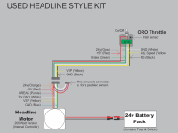
I have purchased a used e-bike kit similar to a Cyclone kit. It uses a 200 Watt Headline Motor (with an internal controller) and an Oro brand throttle.
I am currently planning the installation of this system to a flat bar road bike. I have purchased a Cycle Analyst (version 2.2) and wish to connect the CA's limiting functions. I also have some reed switches to function as brake cut out switches. My objective is to simplify and minimise the amount of wiring on the bike.
I have prepared two diagrams – one being the kit as purchased, and the other being the planned installation. I need some input to verify my proposed circuits.
In particular, I am confused about the ground connections and whether it is ok to connect ground wires (24V & 5V) together at various locations.


I intend to post updated diagrams as feedback is given, and hope that these might help others in the future.
I have purchased a used e-bike kit similar to a Cyclone kit. It uses a 200 Watt Headline Motor (with an internal controller) and an Oro brand throttle.
I am currently planning the installation of this system to a flat bar road bike. I have purchased a Cycle Analyst (version 2.2) and wish to connect the CA's limiting functions. I also have some reed switches to function as brake cut out switches. My objective is to simplify and minimise the amount of wiring on the bike.
I have prepared two diagrams – one being the kit as purchased, and the other being the planned installation. I need some input to verify my proposed circuits.
In particular, I am confused about the ground connections and whether it is ok to connect ground wires (24V & 5V) together at various locations.


I intend to post updated diagrams as feedback is given, and hope that these might help others in the future.


