Headway 4 cell booster pack build

voicecoils

1 MW
Joined
Sep 16, 2007
Messages
2,173
Location
Sydney, NSW, Australia
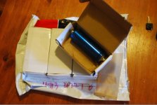
Mark_A_W and I will be building up 4 cell 12v nominal booster packs from Headway 38120S cells that have just arrived. We'll be using 2A Voltphreak single cell chargers.

Here's a few pics to start things out.

I plan to detail how I connect the cells (flattened copper pipe perhaps...), connections for the single cell chargers, etc

Questions, test requests, suggestions?

Cheers! 8)
 

Attachments

  • screwtype-2.jpg
    screwtype-2.jpg
    50.4 KB · Views: 2,655
  • screwtype-1.jpg
    screwtype-1.jpg
    56 KB · Views: 2,656
  • screwtype-3.jpg
    screwtype-3.jpg
    21.2 KB · Views: 2,652
Just in time...my booster lipos are dying.

One puffed up like a porcupine fish....it's cactus.


The Chargers will be interesting. How am I supposed to fit 4 on a Powerboard? They poke out to the left...

I guess 2 powerboards with 2 per board.
 
Oh, I couldn't find any copper strip at work.

Best thing will be to find some copper pipe and flatten it. Or use thick wire.


I'm still looking.


How wide are the cells?
 
copper pipe is overkill imo, 14G solid wire should handle 30A easy, make a loop for the screw, flatten it a little if you need it thinner to get all the screw threads engaged, careful with the torque on the cap. BOL, dennis
 
pgt400 said:
How did the cell get to over 3.8 volts ? I thought the lifepo4 chargers cutoff at 3.65 ?

It's charging, see the thin black wires on the ends.

There's a bit of surface charge that's gone a few min after charging. I've just measured the cell in the photo and it's sitting at 3.35V 12hr later without any load on it.
 
Mark_A_W said:
Oh, I couldn't find any copper strip at work.
How wide are the cells?

Cells are 38mm wide and ~150mm long with the screws in.

Ok will look for copper pipe.

Powerboard: The chargers have US plugs. I was thinking of just wiring them all together and then connecting up an Aussie lead. On the other end they terminate in a round typical wall wart type plug. Maybe I can find the female jacks at Jaycar and wire them directly to the pack and tape/glue them down. Then they can just plug and go for charging.

@ dnmun: I was thinking copper pipe for structural reasons as well. Could just wack some ductape around them though 8)
Also, with tightening, they come with spring/split washers. Once you've screwed the split down your done tightening. Makes things easy.
 
pgt400 said:
After reading Garys BMS thread, I beleive his shunt turns on at 3.65 volts? So I would guess the cell voltage (surface charge or otherwise) would never go above 3.65 volts?

I haven't kept up with the Gary BMS thread. Not sure, I'll see what I can dig up.
 
The VoltPhreaks chargers have the CC/CV set a bit higher than what is really needed, which is a minimum of 3.65V. I've got 16 of them and the cutoffs range from about 3.75V up to as high as 3.90. It won't hurt the cells doing this, as far as I can tell.

With LiFePO4 cells, the voltage rises at a slow steady rate, as it charges, until the cell gets to about 3.65-3.70V, which if you stopped there is about about 85% full. Above that point the voltage rises at a much higher rate. It will take only seconds to get to 4.0V, or higher. In order to get the last 15% into the "tank", you need to hold the voltage at somewhere between 3.65-3.70V, and let the current taper off. When it gets down under about 50mA, or so, the cell is about as full as it is going to get. With LiFePO4 cells, the crossover point voltage is not all that critical. I've tested cells using a VP charger that has a crossover set to 3.84V, and then tested the same cells using our BMS, which has a 3.68V crossover point. Once the surface charge is burned off, which with some cells happens on its own, but with others you need to put a very slight load on the cells for a few seconds, to get rid of the surface charge, the cell ends up with the same "full" voltage, and has the same capacity.

-- Gary
 
GGoodrum said:
The VoltPhreaks chargers have the CC/CV set a bit higher than what is really needed, which is a minimum of 3.65V. I've got 16 of them and the cutoffs range from about 3.75V up to as high as 3.90. It won't hurt the cells doing this, as far as I can tell

Thanks for dropping by Gary :p This is basically what I wanted to hear. They're nice simple units.

I'm not planning on using a BMS with this little 4 cell pack. I'll just use the single cell charges to charge individually and have LVC set on my Cycle Analyst of the combined packs. either 12v10a + 36v10ah or 12v10ah + 72v10ah.
 
pgt400 said:
VC, What do you mean by combined packs? Are you planning to use 12v 10ah in seires with another pack of lifepo4's?

Yes as indicated above. Either:

12v10Ah (screw pack) + 36v10Ah (tab pack w/BMS) = 48v10Ah

OR

12v10Ah (screw pack) + 36v10Ah (tab pack w/BMS) + 36v10Ah (tab pack w/BMS) = 84v10Ah

All blue headway cells in all packs.

* "tab pack" == blue cells tab welded together by Headway.
 
View attachment 1

Going to use my trusty US 6 socket powerstrip. Just enough places for my 4 single cell chargers and two 36v lifepo4 headway chargers (if I can fix 1 of the 2 36v chargers that I broke).

I need to hacksaw off the flanges of the single cell chargers to get them all to fit on the board. Will mount them opposing eachother for better heat dissipation.

copper_strips.jpg

Mark_A_W, want these copper strips from an unrelated non-US powerstrip? They firmly hold the charger prongs. They just need an Aussie lead connected to the ends and somehow protected from children fingers :shock:
 
pgt400 said:
How many miles have you gotten from your first headway pack? I heard several complaints on the paper covered units, sounds like they have improved with the blue covered units.

This is a bit off topic but...less then 100km from the packs, probably been on the charger less then 10 times so far. Neither of the ebikes are road ready for daily use. Still building and testing. Mostly an issue of the amount of time I can work on them.

Fortunately the batteries have been the one straightforward 'plug and play' aspect of the bike.

When I get my X5 up and running I'll be able to draw 40A @ ~80v and find out what kind of voltage sag the packs/cells have at 4C discharge rate.
 
With a 10Ah headway pack I would stick to 30 amps.

You'll sag it too far. For 40A you need 20Ah.


(I'm hunting around for a US powerboard).
 
pgt400 said:
How many miles have you gotten from your first headway pack? I heard several complaints on the paper covered units, sounds like they have improved with the blue covered units.


I have a paper celled 48v 10Ah Headway pack. I've had it for a couple of months, and it's done over 1000k.


Overall it's been really good, but there have been a couple of issues;

1. One of the tab welds was disconnected when it arrived. Getadirtbike tig welded it (very delicately) and it has been fine. With the screw cells this is moot.

2. The BMS trips when it shouldn't. If you "let go" of the throttle the BMS will trip. My brother's headway pack does this too, with a completely different motor and controller. I have found that if I "wind back" the throttle, then it's ok. but the BMS is being replaced under warranty, it just takes time...

It's good to 30amps.

The Headway cells are great. The welding and BMS need improvement.
 
Ok, some progress.

Dodgy sticky tape and flattened copper water pipe pack. Ready for the ride to work tomorrow - will do it properly on the weekend (need a 5 pin connector for the chargers and a US powerboard).

There are 4 Deans connectors because these cells replace four RC lipo packs. Cooked the packs last night on my ride :twisted: They swell up like sausages when you drain a 3 cell lipo to 3v. No they didn't catch fire.
 

Attachments

  • P1010467 [1280x768].JPG
    P1010467 [1280x768].JPG
    116.8 KB · Views: 1,623
  • P1010468 [1280x768].JPG
    138.7 KB · Views: 1,616
  • P1010470 [1280x768].JPG
    P1010470 [1280x768].JPG
    146.6 KB · Views: 1,616
Ok, I rode to work. 15k in 24 minutes (uphill, but a tailwind today), no problemo.

Booster pack worked well, it didn't drop below 12.5v (from 13.3v charged), but I only used 3Ah.


Thanks for organising the cells Abraham.
 
No worries.

Paid 6th Jan, cells dispatched the same day. Flew from Hong Kong to Australia and was cleared all on the 10th (a Saturday). Delivered early Monday (12th).

Bank charges were an unexpected PITA that cropped up after the fact but otherwise a transaction and turnaround time that was pretty faultless.

Thanks Headway!

Mark, If you only used 3Ah you must have only engaged the pack occasionally right? How are you switching it on for the 'boost'?
 
No, the pack is not switchable, and I was full throttle (I can remove it with some shorted Deans Connectors).

15k = 3Ah or so.

30k = 6 or 7Ah.

9Ah gives me about 40k, then LVC happens.

Edit, I get what confused you - I meant the pack didn't sag much, but it was only drain 3Ah so far. Will see what happens at 7Ah.


Did you get more banks fees?

Do you want me to split them with you?
 
Mark_A_W said:
No, the pack is not switchable, and I was full throttle (I can remove it with some shorted Deans Connectors).

15k = 3Ah or so, 30k = 6 or 7Ah, 9Ah gives me about 40k, then LVC happens.

Got it. I plan to simply keep it connected.
So essentially with full throttle on the whole way all that happens is: hills -> increase current, mad pedaling -> decreases current.

Did you get more banks fees?
Do you want me to split them with you?

There were 3 errors and oversights on my part:

1) I incorrectly assumed HSBC would not charge me since it's the most fee-free bank I've ever had.
2) When the payment was processed there was an "oh by the way, you've been charged $20 for the transaction". When I emailed you I gave you the price which I said included this fee but I actually forgot to add it.
3) A few days later another line item fee was deducted, this time $30 which was totally unexpected. The charges aren't clearly labeled as to what they represent. I can only assume that one fee is for converting currency and the other is to process the telegraphic transfer.

I won't burden you with these add on costs (or half of them) since it was my error not to fully determine them and outline the costs upfront before the purchase was made.

As a general comment to other E-S readers, an attractive $/cell price is only one factor in an order if you choose to purchase direct yourself. If you're making a very large order (container(s) scale) it will be the most important factor, however for a small order shipping, handling, banking, and possibly customs/clearance fees cannot be ignored.
 
Mark_A_W said:
Ok, some progress.

Dodgy sticky tape and flattened copper water pipe pack. Ready for the ride to work tomorrow - will do it properly on the weekend (need a 5 pin connector for the chargers and a US powerboard).

There are 4 Deans connectors because these cells replace four RC lipo packs. Cooked the packs last night on my ride :twisted: They swell up like sausages when you drain a 3 cell lipo to 3v. No they didn't catch fire.

I am curious to see long term how these cells hold up, they are certainly a lot more attractive price wise then PSI (about 1/2).

You may want to rethink your packaging. By using solid copper to connect the cells you are putting a lot of strain on the stud. I really don't think that this is a good thing for them, they are not designed to carry a structural load. There is some evidence that on the PSI/Lifebatt cells this has caused them to leak and lead to loss of cell life.
 
i have already worried openly on several threads that heavy gauge copper plate, and stiff connections between cells attached at the caps may lead to failures, and i think that had something to do with the large 5P headway pack that was built in britain right after the new screw caps came out last year.

i still think it is best to secure the caps together using relatively thin and flexible copper ribbon, with a fold in the middle to prevent torque transmitting forces from one cell to the next or jamming the weight of the pack down onto the caps, which i think was how the 5P pack was damaged, but they could be damaged by different rates of expansion of the cells also. once one cell goes it will pull the others in parallel down also, and 14G wire should be more than adequate to carry the 30A or so max expected from the headway 10Ah cells. maybe 14G stranded soldered into small lugs would be best or easiest to find. all jmho
 
Back
Top