Help, new 116 programer pinout.

tron

100 mW
Joined
Apr 15, 2008
Messages
42
Location
Eastern Canada
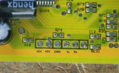
I've been trying to program my 48volt 30amp Keywin(e-crazyman) controller. I've downloaded the new 116 software, installed the new driver for the cable and I've tried changing the wires every way I could think of with no luck. Does anyone have a picture of the pinout on this particular board. I would assume the 72volt's board is the same. I know that DoctorBass had a problem and solved it but I'm at my wits end. The 5v is indicated on this board but the Tx and Rx is not and I believe Methods said the ground was good for the negative. I've even checked the 5volts coming out of the USB and it's good. HELP PICS POST anyone!:x
 
I got this picture from DoctorBass (thanks Doc!). Does anyone have a picture of the USB cable. The pinout seems to have 5 pins and the cable I got from Keywin has 4 wires? :?
 

Attachments

  • pc%20connection%20low%20res.jpg
    pc%20connection%20low%20res.jpg
    25.3 KB · Views: 2,427
Funny the cable I got from keywin had 5 wires only 4 were used and all were in the wrong order.
 
The Chinese documentation from Xie-Chang (maker of the board) says to first click on "Start Transmit" in the Parameter Designer program, then install the programming cable starting from the left (+5V) side and moving towards the right (kind of a rocking motion). It sounds strange, but it seems to work.

--Bill
 
Thanks Stator, I'll try this.
 
I think one of the +5V connectors (first one) is a program enable, it need to be hooked up to a momentary switch. You could make up your own cable out of an old USB cable anyways...
 
Ya, I'm still having trouble with it. I put a momentary switch on the second 5v. I'll try putting the momentary switch on the first 5v from the left.
It would be neat if someone posted a photo of their successful setup. Is the 5v shared from the first one?
 
Damn!
I just grounded one of my Caps. "CRACK" the wife said what's that! I've been opening and closing the case so often I forgot to discharge them. I'm about ready to give up on programing this P.O.S. I think the problem comes down to when I soldered the header on the board and bent up the pins something might have broke on the board. The program (Keywin Lab) has no problems whatsoever and the COM ports I choose seem OK. It just doesn't connect to the damn board. I tried the momentary switch, I've tried rocking the pins, I've tried the other 5v, and even reinstalling the Prolific driver for the USB cord many times. I've tested the 5v and Neg wires on the USB cord and they're good. I always pressed "START TRANSMIT" before connecting and never got a confirmation. What else can I try?
Does anyone have one last shred of wisdom to throw at this because either I give up and purchase a new controller or run this one as is (sans regen), if I didn't blow the low voltage side (oops) with my Cap discharge. :shock:
 
I believe it's an EB212 but I'll try to post some pictures.
 
That one should work, and the pin out matches what was posted earlier.
Here is a picture of the cable I am using and a close-up of the wiring.
White -> White
Red -> Red and Orange
Green -> Yellow
Black -> Black

usb.JPG

usb2.JPG
 
Hi tron,

Did you find the problem ?
I'm having the same trouble in the moment with an EB206-A-2 board I just bought recently.

Thank's

Thomas
 
I'm still having problems, but noticed that stator's got a yellow cable that I don't have. I'm going to work at it tonight and report back. I'm going to open up my USB prolific chip again and trace back the cables.
Hey stator, thanks for the pics. Have you ever opened up your USB cord? Mine seems to start with four connections and end with four connections. Just different color wires. I'll try to get some pics out tonight. I really appreciate the help so far.
 
Hey stator,
Yours seems to have the red and orange sharing the 5 volt output. I'm looking at your picture and it seem to have four cables to start out with and the orange and red shared?
 
Just a short note that programming my EB206-A-2 works now fine. The problem was the USB-Adapter. After I changed
the USB adapter it worked.

Thomas
 
Here's some pics. But I don't think it'll help. I'm narrowing it down to a faulty Prolific USB cord. I believe I'm having the same problem that bapou was having.
 

Attachments

  • Picture 002.jpg
    85.3 KB · Views: 1,375
  • Picture 010.jpg
    66.1 KB · Views: 1,375
Thanks stator! :D I put the switch on the black ground wire and Voila!
I now have a 35amp "116" controller with braking regen.
I feel that this (slow but steady) build is almost complete. I just have to
calibrate my Cycle Analyst to have the finished product. 8)
 
Back
Top