martinev
10 W
- Joined
- Jun 24, 2022
- Messages
- 89
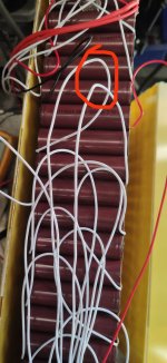
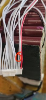
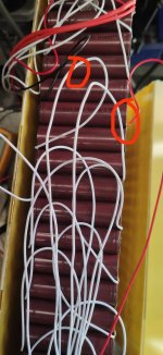
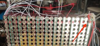
Hi can someone give me where to check next please
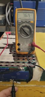
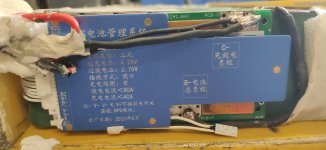
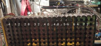
I've just replaced our original Bms for this new BMS but battery positive meter probe and meter probe to negative connection it shows 76v .
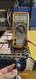
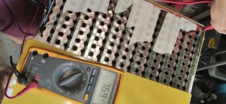
Then probe on battery positive red and probe to Bms B- shows 72v but probe to positive red and probe to C- is 6.2v ? Thanks
I've just replaced our original Bms for this new BMS but battery positive meter probe and meter probe to negative connection it shows 76v .
Then probe on battery positive red and probe to Bms B- shows 72v but probe to positive red and probe to C- is 6.2v ? Thanks