
alan6770
100 µW
- Joined
- Jun 27, 2018
- Messages
- 9
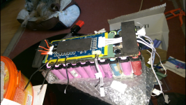
Hi members can anyone give me info and guidance please.lol.
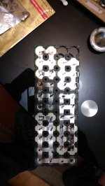
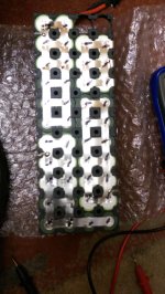
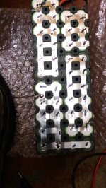
I know that the 3 small red positive wires solder to the battery positive , and the 3 negative wires to the opposite side negative cells ,
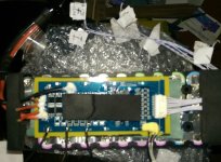
But can anyone, help me out please with the process and order in the bms wires..I've labelled ..thanks
I know that the 3 small red positive wires solder to the battery positive , and the 3 negative wires to the opposite side negative cells ,
But can anyone, help me out please with the process and order in the bms wires..I've labelled ..thanks
Attachments
-
 Screenshot_20240308-125824.png2.6 MB · Views: 4
 -
 Screenshot_20240308-111322.png2.2 MB · Views: 4
 -
 Screenshot_20240308-111455.png1.8 MB · Views: 4
 -
 IMAG0127.jpg762.1 KB · Views: 4
 -
 IMAG0128.jpg965.3 KB · Views: 4
 -
 IMAG0116.jpg977 KB · Views: 4
 -
 IMAG0117.jpg1,014.5 KB · Views: 5
 -
 IMAG0187_1.jpg291.4 KB · Views: 4
