Help Understanding the Wiring Diagram of the Lights

Jay-Cee

100 mW
Joined
Jul 7, 2024
Messages
45
Location
France
Hello everyone!

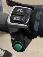
I want to replace my original controller (48V, 25A) with a JN model while keeping my entire electrical bundle and equipment, including my lights and horn, as well as the switch that allows me to choose between crossbeams and headlights and use the horn.

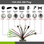
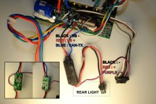
However, I'm having a matching issue between the JN controller's connectors, which include two 2-pin JST SM connectors for the lights, and the wiring of my equipment. To facilitate understanding, I've created a diagram of the signals sent by my original controller.

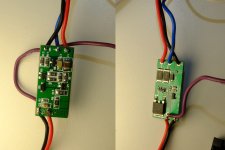
Could someone explain the role of this small electronic circuit (present in the controller)?
How should I wire my lights with the JN controller to get them working with the screen and adjust the intensity with the command?

Thank you in advance for your help!
Shema connecteur light (light).jpg
IMG_0869.JPGCommande lumiere et klaxon.jpg
 
That first pic shows your old controller, right? The new controller has two 2 pin connectors for your lights. So that's where you lights will connect.
You are not showing us where your old controller powered the headlight (front light), but I don't think it matters.
 
That first pic shows your old controller, right? The new controller has two 2 pin connectors for your lights. So that's where you lights will connect.
You are not showing us where your old controller powered the headlight (front light), but I don't think it matters.
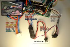
Yes, that's right! The front light doesn't have a JST SM 2-pin female connector like the rear light. The front light is connected via the 'purple' wire in the 5-pin female connector. This 5-pin female connector is itself connected to the main cable (identified by the red arrows) that links the brake levers, the throttle, the display, and the front light (and the horn).

My question is: how should I wire the lights to the new controller?
  • Can I reuse the MOSFET? But I wouldn't be able to connect the signal wire (blue) to the CAN-TX terminal.
  • Or should I use a relay? And in this case, which relay should I use?
Shema connecteur controleur (light).jpg
LIGHT.jpg
 
The old controller doesn't have an onboard MOSFET to switch the lights on and off, so it's using an external one. It's very simple. A MOSFET is like a switch. On your one, when the blue wire is switched on by the CPU, it switches the MOSFET on, which connects the incoming red battery wire to the outgoing red for the lights. The black ground runs straight through for the lights and is also used for the pcb ground. In other words, when you switch on the lights on your control panel, you get battery voltage on the two-pin connector, and the power is cut when you switch off. It also powers the purple wire at the same time, whatever it's used for (repeater or back light, or maybe the purple is the front light and the red is the back light).

It looks like the other components on the external pcb are for overload protection so that you don't get a fire when your lights wires get shorted.

Most controllers have the MOSFET for the lights on the main pcb, so you only get a 2-pin connector, which you have to add parallel wires to if you want both front and back lights.

Personally, I'd never use a controller to switch lights. They can give all sorts of problems. In particular, most have a low power rating for the lights, so when you fit decent ones, it overloads and blows the transistor. It's much better to wire your lights directly to the battery and use your own switch and fuse or use a separate rechargeable battery for 12v lights. In other words, don't try and fit a big headlight to your new controller. I doubt that it'll work, and you can sometimes wipe out the whole controller when the transistor blows.
Based on what I have read and learned, the controller I currently use would use the CAN (Controller Area Network) bus communication protocol.

The new controller would use the UART (Universal Asynchronous Receiver Tx/Rx) communication protocol.

I note your warning about powering the lights, I'll look into it later. For now, the new controller has 2 connectors dedicated to the lights. Do you think they are equipped with a MOSFET? This would allow me to connect my lights directly. Or if not, if I place the MOSFET on the new controller, will it work? since the signal will not be connected to a CAN-TX terminal.
 
Last edited:
The old controller doesn't have an onboard MOSFET to switch the lights on and off, so it's using an external one. It's very simple. A MOSFET is like a switch. On your one, when the blue wire is switched on by the CPU, it switches the MOSFET on, which connects the incoming red battery wire to the outgoing red for the lights. The black ground runs straight through for the lights and is also used for the pcb ground. In other words, when you switch on the lights on your control panel, you get battery voltage on the two-pin connector, and the power is cut when you switch off. It also powers the purple wire at the same time, whatever it's used for (repeater or back light, or maybe the purple is the front light and the red is the back light).

It looks like the other components on the external pcb are for overload protection so that you don't get a fire when your lights wires get shorted.

Most controllers have the MOSFET for the lights on the main pcb, so you only get a 2-pin connector, which you have to add parallel wires to if you want both front and back lights.

Personally, I'd never use a controller to switch lights. They can give all sorts of problems. In particular, most have a low power rating for the lights, so when you fit decent ones, it overloads and blows the transistor. It's much better to wire your lights directly to the battery and use your own switch and fuse or use a separate rechargeable battery for 12v lights. In other words, don't try and fit a big headlight to your new controller. I doubt that it'll work, and you can sometimes wipe out the whole controller when the transistor blows.
What's all this talk about a MOSFET? The board you and the original poster keep referring to as MOSFET clearly has 'DC-DC' written on it. It does have an input labeled 'E' on it. I'm guessing that is where it's switched on ('E' for 'enable'). But it doesn't matter because the new controller already has dedicated 2-wire connectors for the headlight and the tail light. So this DC-DC board will no longer be used.

Jay-Cee, as you said the purple wire coming from the plus + output of the old DC-DC board and running to the main connector was feeding your headlight. So the tail light connector from the new controller should connect to the two wires of your tail light, and the plus + wire of the new head light connector should feed the wire that was fed before by the purple wire. If you are unsure about the voltage of your existing lights, and the lighting output voltage of the new controller, measure those voltages on the old and the new system.
 
Last edited:
What's all this talk about a MOSFET? The board you and the original poster keep referring to as MOSFET clearly has 'DC-DC' written on it. It does have an input labeled 'E' on it. I'm guessing that is where it's switched on ('E' for 'enable'). But it doesn't matter because the new controller already has dedicated 2-wire connectors for the headlight and the tail light. So this DC-DC board will no longer be used.

Jay-Cee, as you said the purple wire coming from the plus + output of the old DC-DC board and running to the main connector was feeding your headlight. So the tail light connector from the new controller should connect to the two wires of your tail light, and the plus + wire of the new head light connector should feed the wire that was fed before by the purple wire. If you are unsure about the voltage of your existing lights, and the lighting output voltage of the new controller, measure those voltages on the old and the new system.
It's true that the use of the term MOSFET is completely incorrect, as it is a DC-DC converter. However, its explanations are clear and align with yours.
 
No, no, unless I misread his (I assume) post, he says that board connects your lights to the battery voltage. Expensive mistake.
As I need to translate, I won't be able to confirm, but in any case, I had understood that the D+ placed at the output of the DC-DC is 12V, and that the BLUE wire was the signal emitted by the screen when I turn on the lights.
 
I winged wiring my lights by splicing red and black to the middle size black and red wires and then I cracked open my bike display which is some crappy g51 and checked to see what colour wire was soldered into what pcb code -so since most displays if you hold the top button high beam indicator comes up on the screen I wanted to utilise that and I think I read somewhere here that tx or rx or ds is either sending a signal or receiving a signal in any case if your desperate or for fun trial and error and remember what colour wire it is in the Juliet - for me yellow is tx and green is Rx and blue is ds . I simply spliced my lights signal wire into either blue or green ( I'm 80% sure it was green rx) so my lights turn on now when I turn the display on and the high beam thing never worked out.
What's good is you already have a switch with the horn button and the 2 light switches , so if u open that switch up you will see where each wire goes and you will be able to splice horn to the horn wire. Also because I'm assuming you have some horn/light in one unit if you didnt have a switch what would happen like it did to me was when you turn display on the lights would come on but so did the horn continuously was only able to resolve that after I bought a switch now everything works perfectly . I even added rear indicators by pretty much using the same technique red black splice to controller then hit a switch with the buttons one wire on left one wire on right and the signal wire spliced to where I spliced the signal wire with the light and horn .
 
Back
Top