Hi everyone,
I've had the fortune of getting my hands on a somewhat large amount of sensored BLDC motors from old Segways. I've been documenting them a bit on GitHub here.
Right now I'm facing an issue that the various ESCs I have at my disposal all expect a binary/digital hall sensor, but the one on these motors are analog.
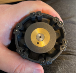
To help make the motors into usable sensored BLDC motors for me, I've been looking into replacing the PCB and adding new hall sensors, but since I've never done this before I have no clue how to even approach this. I took one of the PCBs off to see how the current ones were working, and it turns out the motor has a permanent magnet on it's rotor, that is used to sense it's position. Here's how that looks.
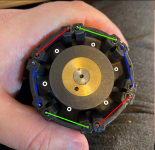
The motors have a double redundancy so they have twice the windings and twice the hall sensors, but I just need them to work as normal motors, so for me all I need is 3 hall sensors. Here is how the different pins are connected and the white dots are where the hall sensors approximately were before, which is 60 degrees apart.
How should I approach picking the right hall sensor for this motor? Can I just pick any digital ones? Do I need to adjust the distance to get a proper duty cycle? What else should I consider? I have no specs on the magnet.
Are there alternative solutions? I did consider making an adapter board instead with some schmitt triggers to make the analog sensors digital.
I appreciate anyone that has read this far and any help I might get.
EDIT:
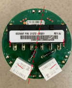
I managed to grab a picture of the existing hall sensors, but I can't find any part information.

EDIT2:
I got some help identifying the part. It appears to be the following part:
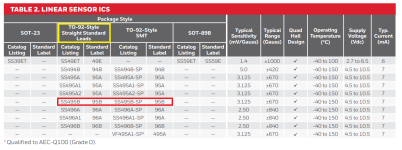
Giving some statistics like a range of ±670 Gauss. I wonder if I can just look for a digital hall sensor with the same range.
I've had the fortune of getting my hands on a somewhat large amount of sensored BLDC motors from old Segways. I've been documenting them a bit on GitHub here.
Right now I'm facing an issue that the various ESCs I have at my disposal all expect a binary/digital hall sensor, but the one on these motors are analog.
To help make the motors into usable sensored BLDC motors for me, I've been looking into replacing the PCB and adding new hall sensors, but since I've never done this before I have no clue how to even approach this. I took one of the PCBs off to see how the current ones were working, and it turns out the motor has a permanent magnet on it's rotor, that is used to sense it's position. Here's how that looks.

The motors have a double redundancy so they have twice the windings and twice the hall sensors, but I just need them to work as normal motors, so for me all I need is 3 hall sensors. Here is how the different pins are connected and the white dots are where the hall sensors approximately were before, which is 60 degrees apart.

How should I approach picking the right hall sensor for this motor? Can I just pick any digital ones? Do I need to adjust the distance to get a proper duty cycle? What else should I consider? I have no specs on the magnet.
Are there alternative solutions? I did consider making an adapter board instead with some schmitt triggers to make the analog sensors digital.
I appreciate anyone that has read this far and any help I might get.
EDIT:
I managed to grab a picture of the existing hall sensors, but I can't find any part information.

EDIT2:
I got some help identifying the part. It appears to be the following part:

Giving some statistics like a range of ±670 Gauss. I wonder if I can just look for a digital hall sensor with the same range.
Last edited:


