izeman
1 GW
damn. never had a bigger wish to be canadian than now!Arlo1 said:I just noticed you are in Vancouver. when do you want to go for a ride?
damn. never had a bigger wish to be canadian than now!Arlo1 said:I just noticed you are in Vancouver. when do you want to go for a ride?
hillzofvalp said:Luke, you would ditch all Leaf systems in doing that right...? Including the bms which I think limits to around 275A? I want to do the same it just sounds like a huge PITA. Please try! :wink:
Have you seen the guts of a OEM leaf inverter? I don't know of any replacement igbts you can just swap out..... Nissan does a lot of stuff to limit the power you can't trick it very easy.charlesmcnall said:hillzofvalp said:Luke, you would ditch all Leaf systems in doing that right...? Including the bms which I think limits to around 275A? I want to do the same it just sounds like a huge PITA. Please try! :wink:
I also was planning on swapping the leaf IGBTs and swapping the current sensors also to make it think it was drawing less current.
Do you know if the battery BMS/ current sensor has a battery over current shutdown? or does it purely just limit phase amps?
Arlo1 said:I just noticed you are in Vancouver. when do you want to go for a ride?
I used a motorcycle sprocket and cut the middle out. Its 48tooth If I can make 110km/h ok with 48 I might make it 24 tooth. But I want to be sure I can read at 210-220 km/h. I will try to get time to test this as well. I have a new code splinter has given me I will test a bit more and share.
I would say splinter gets the credit for the code. I just did a bunch of digging on online and found snipits and put them together till I saw the gauges workingThen I asked for help when I found that was not good enough.

Arlo1 said:Awesome thanks. Today I ground off every second tooth. Part of the reason I want as many teeth as possible is I want to use the speedo to read 0-60 times. I had it up to 160 tonight. More testing tomorrow. After finding some issues with 1 current sensor and the way the signal was getting to the brain I was able to increase the power to 700 phase amps 600 battery and 450 field weakening. At this power I pinned it at 60 and it spun the tires till it hooked up at 100km/h then slamed me into the seat as it rocketed to 160 where I let off the throttle.
Tomorrow I try 750a phase 650a battery and 500a field weakening and slicks !
Thanksfechter said:Wow, that thing really moves!
What about some kind of automatic traction control to keep it from breaking loose?
HighHopes said:grrr... ontario changed registration rules for homebuilts. now must have all the safety things of modern cars such as electronic stability control. now i have to draw a box in my block diagram to include this. bit of a nanny state over here. hope you register your vehicle before the new rulez apply in BC too!
void loop() {
  byte inByte;
  if (Serial.available()) {   //wait for a data request from nextion display and assign to inByte
    inByte = Serial.read();

  }
  if (inByte == 36) {         // if data request is "$" update gauges only
    DashUpdate();
  };

  if (inByte == 33) {         // if data request is "!" update number fields

    LcdUpdate();

  }


}
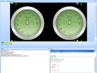
Cool thanks for looking into this.kiwifiat said:I have been playing about with the Nextion editor and simulator and one of things I have noticed is that is really easy to overflow the receive buffer and that once that happens the display does not respond in real time to updates. There is quite a bit of dialog on the Nextion forum about screen updates and it seems that some users have struggles to get more than around 3Hz update rate for more complex gui designs. I setup a mock-up with two gauges and four numerical fields and found that if I update them all at the same time then the display becomes unresponsive. I have added a couple of addition variables to the Nextion design and a timer to trigger requests. The time event is counted and I take a modulus 3 of the count variable and send an update request for the gauges every trigger and an update for the numerical fields once every 3 timer events. This has made the screen much more responsive to updates and the gauges get the priority.
Here is the main loop code I'm running on the arduino end that calls the gauge update function and the numerical field update as requested.
Code:void loop() { byte inByte; if (Serial.available()) { //wait for a data request from nextion display and assign to inByte inByte = Serial.read(); } if (inByte == 36) { // if data request is "$" update gauges only DashUpdate(); }; if (inByte == 33) { // if data request is "!" update number fields LcdUpdate(); } }
Can you tell me if you have the enhanced Nextion 7" or the standard edition? It is a pity we are not a bit closer as it would be really helpful to have access to the actual Nextion device as I am wondering how well the simulator mimics the real thing.
kiwifiat said:
Can you tell me if you have the enhanced Nextion 7" or the standard edition? It is a pity we are not a bit closer as it would be really helpful to have access to the actual Nextion device as I am wondering how well the simulator mimics the real thing.
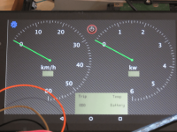
Lebowski said:I see your dial only goes up to a measly 100kW ?
Arlo1 said:Lebowski said:I see your dial only goes up to a measly 100kW ?
Lol yeah.. I am putting 610-620 amps in at 410v under load with plans to go to 750 amps on this setup.
So the KW gauge would need to be higher.
In fact I might change mine around to have an analog Kw and an analog Amp gauge.
+1!grindz145 said:Arlo1 said:Lebowski said:I see your dial only goes up to a measly 100kW ?
Lol yeah.. I am putting 610-620 amps in at 410v under load with plans to go to 750 amps on this setup.
So the KW gauge would need to be higher.
In fact I might change mine around to have an analog Kw and an analog Amp gauge.
This is potentially my favorite project on ES, and generally speaking, I frocking hate cars. It's just that badass!
liveforphysics said:+1!grindz145 said:Arlo1 said:Lebowski said:I see your dial only goes up to a measly 100kW ?
Lol yeah.. I am putting 610-620 amps in at 410v under load with plans to go to 750 amps on this setup.
So the KW gauge would need to be higher.
In fact I might change mine around to have an analog Kw and an analog Amp gauge.
This is potentially my favorite project on ES, and generally speaking, I frocking hate cars. It's just that badass!
Arlo1 said:Lebowski said:I see your dial only goes up to a measly 100kW ?
Lol yeah.. I am putting 610-620 amps in at 410v under load with plans to go to 750 amps on this setup.
So the KW gauge would need to be higher.
In fact I might change mine around to have an analog Kw and an analog Amp gauge.

liveforphysics said:+1!grindz145 said:Arlo1 said:Lebowski said:I see your dial only goes up to a measly 100kW ?
Lol yeah.. I am putting 610-620 amps in at 410v under load with plans to go to 750 amps on this setup.
So the KW gauge would need to be higher.
In fact I might change mine around to have an analog Kw and an analog Amp gauge.
This is potentially my favorite project on ES, and generally speaking, I frocking hate cars. It's just that badass!
Arlo1 said:Knowing the power into the system is very important to me. If all the sudden it's using power when it's not supposed to that's bad VERY bad. Also if the power is low into the system I need to figure out why. Is it a weak battery ? A bad connection? Cold batteries? Something set wrong in the controller? It's very useful. When I went to race the 370z I forgot to set field weakening to 450amps and I could see the kW fall off at 100km/h...
But also at full throttle at 130km/h it was still using 60kw so I need to look into that as I expected it to be 20-30kw at 130km/h
Arlo1 said:Lol cool. I will work on mine more later. I like the see though background.
you will notice they don't like to start at 0 lol. Takes some math to make that work.
Also I need to get my amp gauge to zero when I first turn the car on. I will try giving the current sensor a clean regulated 5v exactly first as right now I am letting it get 5v from the arduino supply. That should help a lot.
