Jay64
100 kW
Ok, more newbie questions here. I just got my high current Cycle Analyst and am trying to figure out how to hook it up properly. I went to ebikes.ca and looked at their instructions and this is what they have posted:
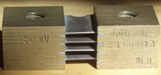
First of all, the markings on the shunt that I recieved are: 50MV on the left side; 600 AMP ESR 60 013 MLB on the right side.

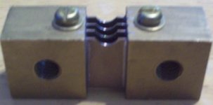
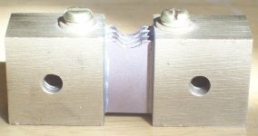
I don't see anywhere on the shunt that designates one side as being + and the other as -. Is that just set on how you wire it in with the battery wires? On that note, how exactly do you wire it in with the battery wires? It has a hole drilled through each side of the shunt with a differnt size thread on either side of the hole.


What is the purpose of the different sized threads and how do you attach the battery to them? I am figuring that I probably just put a ring connector on the battery cable, run a bolt through that and attach that to the shunt. Maybe the smaller thread is used to secure the shunt down???? I realize that these are probably really newbie questions, but I have never worked with a shunt before.
(note: Justin, I'm not trying to steal from your page, just posting up what I am refering to when I am asking these questions.)The High Current model is like the Stand Alone version but without a molded shunt, so that you can attach it to high amperage sense resistors. The blue wires with a ring terminal go to the (-) side of the sense resistor, while the white/orange striped wire goes to the (+) side of the shunt. The remaining orange wire is connected to the positive leads of the battery pack.
First of all, the markings on the shunt that I recieved are: 50MV on the left side; 600 AMP ESR 60 013 MLB on the right side.

I don't see anywhere on the shunt that designates one side as being + and the other as -. Is that just set on how you wire it in with the battery wires? On that note, how exactly do you wire it in with the battery wires? It has a hole drilled through each side of the shunt with a differnt size thread on either side of the hole.


What is the purpose of the different sized threads and how do you attach the battery to them? I am figuring that I probably just put a ring connector on the battery cable, run a bolt through that and attach that to the shunt. Maybe the smaller thread is used to secure the shunt down???? I realize that these are probably really newbie questions, but I have never worked with a shunt before.

