markz
100 TW
*I changed the title*
I am building me a 74V 10Ah pack with five 4S1P (14.8V 5Ah) Turnigy batteries in series = 74V 5Ah, then putting exact setup in parallel to make 74V 10Ah, maybe 15Ah.

Controller will be lyen 18fet 72V nomial 65A current rating. LVC 62.5
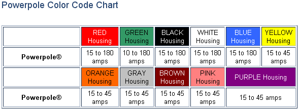
I assume Anderson Connectors are the professional/safer way to go, better then the bullet connectors that come on the Turnigy Batteries.
Those bullet connectors seem to be able to pull apart easily.
Where can I buy Anderson Connectors for cheap, that wont cost a lot to ship, to Canada?
I found these guys http://www.powerwerx.com/anderson-powerpoles/housings-contacts/ Shipping is around $20
Here is my wiring diagram I came up with, are the wire guages correct?
Series -
 https://www.flickr.com/photos/128734122@N04/15647507954/
Parallel -
 https://www.flickr.com/photos/128734122@N04/16084064697/in/photostream/
Who sells BMS's?
BMSBattery has some, but thats BMSBattery.
Here is one 10S/13S/30A/50A Lipo Battery BMS System $18, who knows what shipping will be.
https://bmsbattery.com/search?search_query=bms&orderby=position&orderway=desc&submit_search=&n=87
I can figure out how to hook up the alarms and such if I choose not to got BMS route.
How do I charge this pack?
Genuine IMAX B8plus Charger/Discharger 1-8 Cells (Max 150W, 1-8Series, 7A Charge)
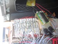
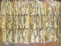
What are the smaller wires coming out of the battery pack? (Used only for charging? and/or BMS?)
I am building me a 74V 10Ah pack with five 4S1P (14.8V 5Ah) Turnigy batteries in series = 74V 5Ah, then putting exact setup in parallel to make 74V 10Ah, maybe 15Ah.
Controller will be lyen 18fet 72V nomial 65A current rating. LVC 62.5
I assume Anderson Connectors are the professional/safer way to go, better then the bullet connectors that come on the Turnigy Batteries.
Those bullet connectors seem to be able to pull apart easily.
Where can I buy Anderson Connectors for cheap, that wont cost a lot to ship, to Canada?
I found these guys http://www.powerwerx.com/anderson-powerpoles/housings-contacts/ Shipping is around $20
Here is my wiring diagram I came up with, are the wire guages correct?
Series -
Parallel -
Who sells BMS's?
BMSBattery has some, but thats BMSBattery.
Here is one 10S/13S/30A/50A Lipo Battery BMS System $18, who knows what shipping will be.
https://bmsbattery.com/search?search_query=bms&orderby=position&orderway=desc&submit_search=&n=87
I can figure out how to hook up the alarms and such if I choose not to got BMS route.
How do I charge this pack?
Genuine IMAX B8plus Charger/Discharger 1-8 Cells (Max 150W, 1-8Series, 7A Charge)
What are the smaller wires coming out of the battery pack? (Used only for charging? and/or BMS?)
")