rsisson
100 W
- Joined
- Oct 18, 2007
- Messages
- 124
all,
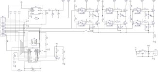
I JUST finished my first pass at a controller.
It's been 20 years since I did this, so there are bound to be edits...
I optically isolated the MosFets from the Controller
I use a 555 to generate BOOST voltage
I used Optical isolation on BOTH the top and Bottom
I used the New On-systems MC33035 Motor controller
I have a jumper in for separating the Motor return and the current sense as one needs to be BIG while the other is just a signal.
I am not sure about the "closed loop" option, it is Mostly there, but I may need a few more components.
I may put in some more zeners near the FETs for protection, and I need to put in some Electrolitic caps for power filtering, along with more filter caps on the power lines and put values on everything, but I wanted to get the outline done first.
As you can see, the component count is very low... and I think it will be robust....
The layout seperates Power and siganl well, so it should be possible to put the FET's on a sub-boardwith a signal cable to it.
This is only DRAFT 1...so feedback is appreciated.