
quasse
100 µW
- Joined
- Sep 1, 2013
- Messages
- 9
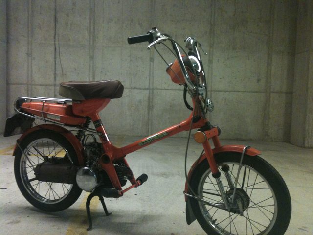
A few years ago I bought a Honda NC50 Express moped hoping to restore it and use it to ride around town. Unfortunately it only ever ran terribly if at all, and upon disassembly it became clear that the previous owner had ruined the engine by running it through dirt and mud without an air filter. The cylinder was scored and many of the bearings were rusted.
After wasting a lot of money and time trying to get the engine running I decided I would much rather convert to to electric instead. I wanted to do as economical of a build as possible using an outrunner, because I had only ever used hub motors before and their cost was prohibitive. Thus started my 50CC to outrunner conversion.
I decided on using a Turnigy SK3 6374. To determine the correct kV rating I did some quick calculations using the transmission ratios and the size of the wheels:
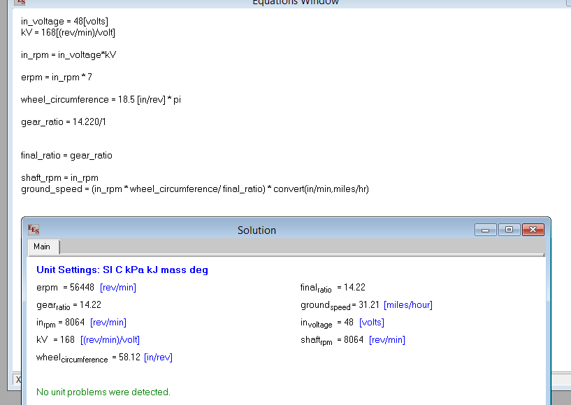
As you can see, with an input of 48v and a 168kV motor, I calculated a ground speed of 31 mph. Of course, in the real world this would be slower due to efficiency losses, but this was in the ballpark of what I wanted. I purchased this motor: https://www.hobbyking.com/hobbyking/store/__18182__Turnigy_Aerodrive_SK3_6374_168kv_Brushless_Outrunner_Motor.html
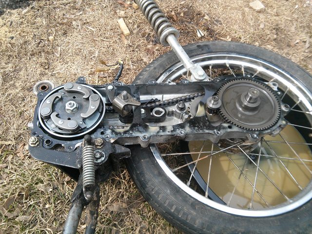
I took apart the transmission:
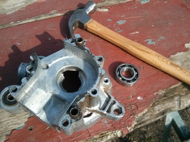
And split the case and removed the piston and jug:
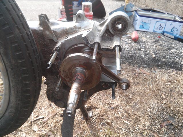
You can see how bad the crankshaft was in the photo above.
I decided that I wanted to use the entire original crankcase, because the frame mounting bushings were cast into the top (you can see one in the photo above), so I was going to have to create some kind of replacement crankshaft to adapt the outrunner to the original clutch and transmission.
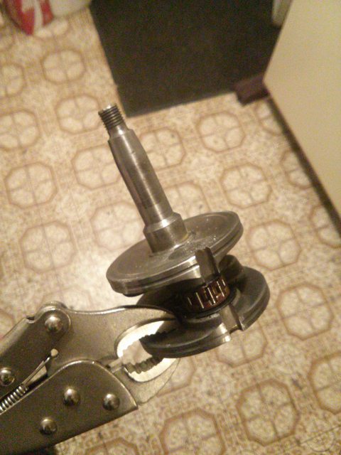
I originally thought I would cut the original crankshaft in half and drill a hole for the outrunner's shaft to fit into. With that in mind I cut everything except the clutch bearing faces off the crankshaft:

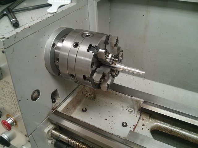
Since I was going to mount the motor on the side of the crankcase opposite the clutch, I would have needed to weld a piece of round stock on to the remaining piece of the crankshaft to bridge the gap. I decided that it would be harder to weld something completely straight that it would be to machine a new one, so I ended up just taking careful measurements of the shaft and creating a new one from aluminum:
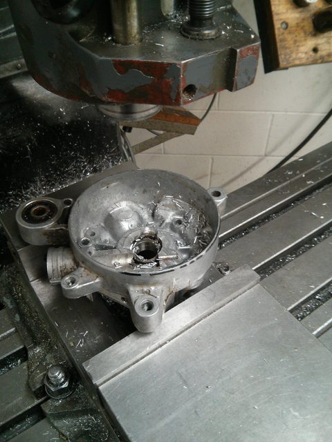
Next up was creating a good place in the non-clutch side of the crankcase to mount a motor. That side originally held the flywheel and ignition system, and had a lot of geometry cast into it. I clamped it in the mill and machined everything flat:
I cut out a sloppy little plate on the bandsaw and drilled a hole for the motor shaft, along with threaded holes for the motor mount:

While I was at it I tapped out the bearing and replaced it with a sealed unit rated for sufficient RPM:
Here you can see the new bearing with the custom crankshaft:
The hole is for the outrunner shaft, I machined a groove into the outrunner shaft and put a set screw inside the new crankshaft to lock them together.
Here is where the piston would have used to be, as you can see it's just a straight aluminum shaft now:
And here is where the clutch would sit (I later threaded the end of the shaft for the clutch lock nut):
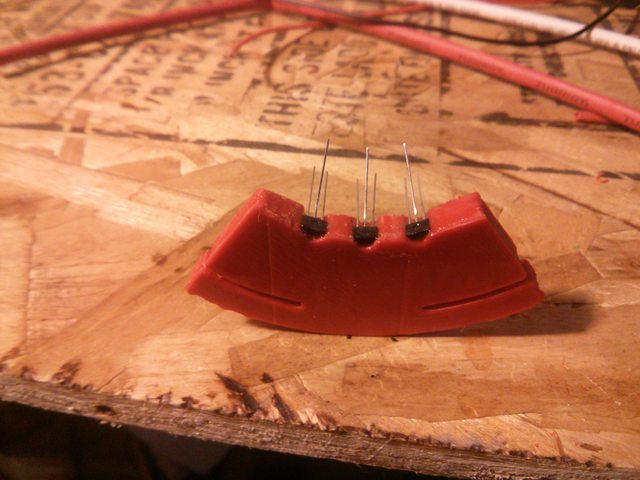
At this point I had pretty much figured out the entire drivetrain and needed to start on electronics. I did not want to use a sensorless controller so I did quite a bit of research into adding external hall effect sensors to outrunners. I found that I needed some way to mount them 17.14 degrees apart around the case of the motor. For this, I turned to 3D printing and whipped up a quick mount on the RepRap:
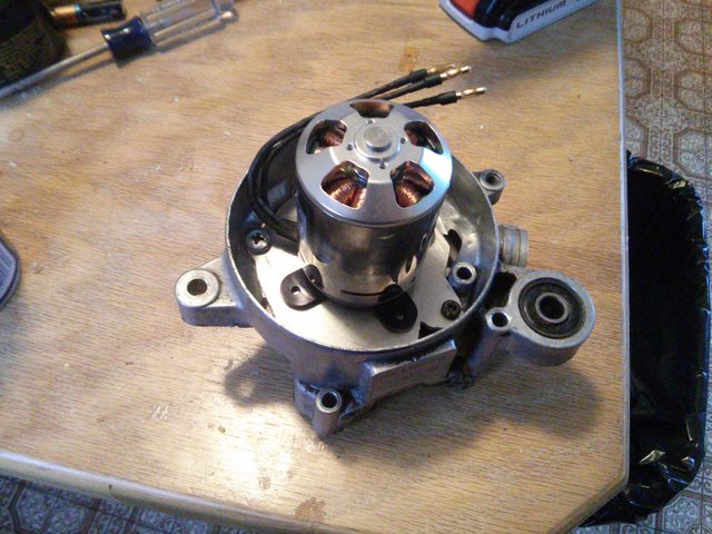
I drilled some holes in a piece of aluminum stock and used that to mount the sensors in the motor side of the crankcase on the same plate I had made earlier:
I'm ashamed of how bad my wiring job is haha, fixing that is the first thing on the todo list once I get things close to done. At this point I was able to reassemble the moped and get everything mounted up! Here's the entire rear end of the moped with the motor installed:

This is where it is today, I'm pretty pleased with how it's turning out. I got around to bolting the rest of the frame on and installing a throttle today, here's the very first run of the motor:
[youtube]b94CECMFl8A[/youtube]
As you can see, my controller is still sitting on the ground and my batteries are in a bike pannier. Fabbing up some kind of battery box is the last thing I need to do before it'll be ready for its first real ride! At this point I'm thinking I'll use the mounting points that were originally designed for the fuel tank (now obsolete of course) and create some kind of aluminum battery box that mounts to them over the rear wheel like you can see in the first picture.
I'm also somewhat unhappy with the adjustability of my hall sensor mounts and the wiring they required. I ordered an Equals Zero designs http://e0designs.com/products/hall-effect-sensor-board/ hall sensor board and adapter and I'll be switching to that when it arrives.
Hopefully this week I'll have time for some work on that, as well as getting some basic stuff like brakes working. I'll update the thread as things happen, but I'm pretty excited to be close to having a rideable moped.
After wasting a lot of money and time trying to get the engine running I decided I would much rather convert to to electric instead. I wanted to do as economical of a build as possible using an outrunner, because I had only ever used hub motors before and their cost was prohibitive. Thus started my 50CC to outrunner conversion.
I decided on using a Turnigy SK3 6374. To determine the correct kV rating I did some quick calculations using the transmission ratios and the size of the wheels:
As you can see, with an input of 48v and a 168kV motor, I calculated a ground speed of 31 mph. Of course, in the real world this would be slower due to efficiency losses, but this was in the ballpark of what I wanted. I purchased this motor: https://www.hobbyking.com/hobbyking/store/__18182__Turnigy_Aerodrive_SK3_6374_168kv_Brushless_Outrunner_Motor.html
I took apart the transmission:
And split the case and removed the piston and jug:
You can see how bad the crankshaft was in the photo above.
I decided that I wanted to use the entire original crankcase, because the frame mounting bushings were cast into the top (you can see one in the photo above), so I was going to have to create some kind of replacement crankshaft to adapt the outrunner to the original clutch and transmission.
I originally thought I would cut the original crankshaft in half and drill a hole for the outrunner's shaft to fit into. With that in mind I cut everything except the clutch bearing faces off the crankshaft:
Since I was going to mount the motor on the side of the crankcase opposite the clutch, I would have needed to weld a piece of round stock on to the remaining piece of the crankshaft to bridge the gap. I decided that it would be harder to weld something completely straight that it would be to machine a new one, so I ended up just taking careful measurements of the shaft and creating a new one from aluminum:
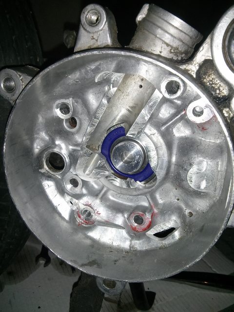
Next up was creating a good place in the non-clutch side of the crankcase to mount a motor. That side originally held the flywheel and ignition system, and had a lot of geometry cast into it. I clamped it in the mill and machined everything flat:
I cut out a sloppy little plate on the bandsaw and drilled a hole for the motor shaft, along with threaded holes for the motor mount:
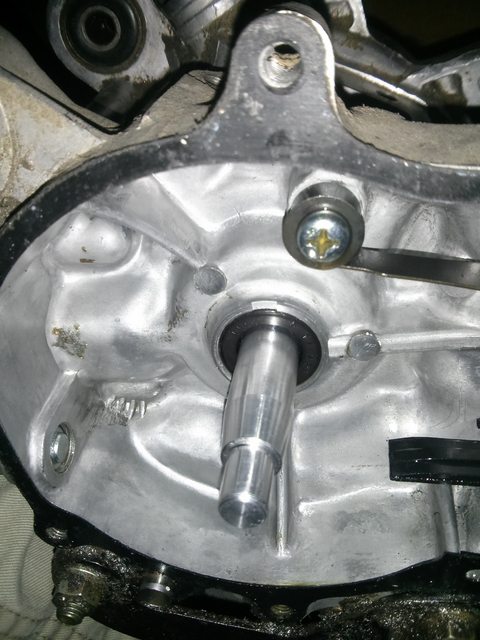
While I was at it I tapped out the bearing and replaced it with a sealed unit rated for sufficient RPM:
Here you can see the new bearing with the custom crankshaft:
The hole is for the outrunner shaft, I machined a groove into the outrunner shaft and put a set screw inside the new crankshaft to lock them together.
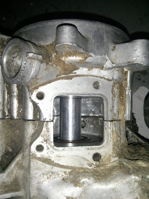
Here is where the piston would have used to be, as you can see it's just a straight aluminum shaft now:
And here is where the clutch would sit (I later threaded the end of the shaft for the clutch lock nut):
At this point I had pretty much figured out the entire drivetrain and needed to start on electronics. I did not want to use a sensorless controller so I did quite a bit of research into adding external hall effect sensors to outrunners. I found that I needed some way to mount them 17.14 degrees apart around the case of the motor. For this, I turned to 3D printing and whipped up a quick mount on the RepRap:
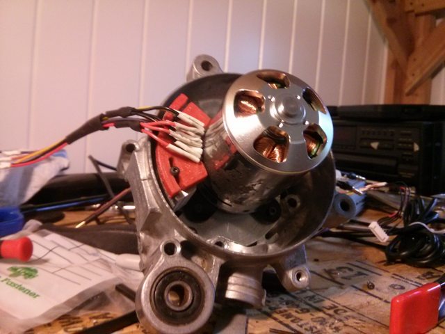
I drilled some holes in a piece of aluminum stock and used that to mount the sensors in the motor side of the crankcase on the same plate I had made earlier:
I'm ashamed of how bad my wiring job is haha, fixing that is the first thing on the todo list once I get things close to done. At this point I was able to reassemble the moped and get everything mounted up! Here's the entire rear end of the moped with the motor installed:
This is where it is today, I'm pretty pleased with how it's turning out. I got around to bolting the rest of the frame on and installing a throttle today, here's the very first run of the motor:
[youtube]b94CECMFl8A[/youtube]
As you can see, my controller is still sitting on the ground and my batteries are in a bike pannier. Fabbing up some kind of battery box is the last thing I need to do before it'll be ready for its first real ride! At this point I'm thinking I'll use the mounting points that were originally designed for the fuel tank (now obsolete of course) and create some kind of aluminum battery box that mounts to them over the rear wheel like you can see in the first picture.
I'm also somewhat unhappy with the adjustability of my hall sensor mounts and the wiring they required. I ordered an Equals Zero designs http://e0designs.com/products/hall-effect-sensor-board/ hall sensor board and adapter and I'll be switching to that when it arrives.
Hopefully this week I'll have time for some work on that, as well as getting some basic stuff like brakes working. I'll update the thread as things happen, but I'm pretty excited to be close to having a rideable moped.


