How do you measure cells in LiFePo4 Pack

Hiconic

100 mW
Joined
Apr 25, 2013
Messages
41
Location
Cairns, Qld.
Hi guys,

I'm new to E bikes and I'm about to finally get my bike back on the road again for another test ride. I've had a couple of issues with faulty controllers and such but I think I've got it all sorted out now. One thing that I need to find out though is how do you measure individual cells (for balancing charge) when the battery pack is sealed 36v-12ah-lifepo4-battery-.jpg is it possible to measure cells without breaking open the pack, I really wanted to keep it as a sealed pack so as to negate any faults occurring from accidental damage when doing measurements. I've got a Ping charger 36 Volt 5 Amp LiFePO4 Charger.jpg so can I rely on this charger to do the balancing charge or is it a bit more involved than just that? I haven't approached this before so I don't want to ignore the process as I know how important it is to make sure cells are balanced for extended battery life.

Regards
Hiconic
 
That looks to me like a LIFPO4 battery with Headway cells inside. If it is from bmsbattery.com, it has a BMS inside the pack, which balances the cells on every charge. Which means you don't need to worry about balancing them. If it is a Ping charger, it is probably set rather high for the BMS in the pack, which normally uses 58.4 or lower voltage to charge. Not sure if it matters, but that could be a bit high for Headway cells. Is there any reason to be concerned about the health of the pack? Otherwise I wouldn't open it up. It is possible to "dial down" the charging voltage of the charger with one of the potentiometers inside the charger.
 
Your pack needs balance leads. In the future, I recommend either only buying packs that come with balance leads or requesting balance leads be added to the pack before it is shipped to you. Checking the balance of a pack is a very important thing to do I think, I check mine once in a while with a cellog. You might be able to add balance leads to your pack, but you'll certainly need to gain access to the BMS and such. I don't know how you'd do that exactly though, you might be able to simply splice the wires coming from the BMS.
 
chvidgov.bc.ca said:
That looks to me like a LIFPO4 battery with Headway cells inside. If it is from bmsbattery.com, it has a BMS inside the pack, which balances the cells on every charge. Which means you don't need to worry about balancing them. If it is a Ping charger, it is probably set rather high for the BMS in the pack, which normally uses 58.4 or lower voltage to charge. Not sure if it matters, but that could be a bit high for Headway cells. Is there any reason to be concerned about the health of the pack? Otherwise I wouldn't open it up. It is possible to "dial down" the charging voltage of the charger with one of the potentiometers inside the charger.

Yep it's a BMS battery and it's supposed to have a BMS inside to handle the cells, but just not sure if it's the real deal or not. Hard to trust something you can't see or access. The ping puts out around 45V when charging, I run it through one of these dual-display-voltage-voltmeter.jpg then into the battery so I can monitor what's happening.

The problem with the ping charger is everything inside (each end) is sealed in with some type of white sealant and it looks pretty daunting a job to attack without something going wrong when attempting to get into it, so I don't really want to touch it.

Regards
Hiconic
 
bowlofsalad said:
Your pack needs balance leads. In the future, I recommend either only buying packs that come with balance leads or requesting balance leads be added to the pack before it is shipped to you. Checking the balance of a pack is a very important thing to do I think, I check mine once in a while with a cellog. You might be able to add balance leads to your pack, but you'll certainly need to gain access to the BMS and such. I don't know how you'd do that exactly though, you might be able to simply splice the wires coming from the BMS.

When I was shopping around on the internet for batteries I hadn't seen any with dedicated balance leads, just leads for motor and leads for charger. It really would help if they did have them as I don't like the idea of breaking open the pack just to see if the BMS is working correctly and potentially causing problems when doing so. " If it aint broke, don't fix it! " is my motto, but with these batteries it's essential to know what's going on with the cells. Thanks for the input.

Regards
Hiconic
 
Oops...sorry...my voltage references were based on the idea your battery was 48V nominal, rather than 36 nominal. On my Headway packs I can just probe each cell directly with a voltmeter on the positive and negative sides of each cell can. I'm pretty sure your pack has balance leads in it, going to the BMS, which you will soon see when you open it up.
 
Only way to measure the cells is going to be to unwrap it. But if you charge to and keep a level equal to 3.65v per cell or more, you don't have any problems to worry about. So I'd just keep an eye on the main pack voltage for now. Then perhaps open it up much later on if the pack seems to drop too much voltage overnight, like down to a 3.4v per cell average.

Opening the ping charger should not be that hard, If the case is the same as Mine, you undo the end covers, then slide the top off. All those screws down the side, leave them alone.
The adjustment pot to fool with to lower the voltage is near the output cord in the corner.
 
Hi Guys,
Well now I've had no other option but to open the pack. I took the bike for a test run after replacing an incorrect controller and after 100yds of running fine, without running on full throttle, she began to smoke up. There was a sudden clunk, drop in speed, then the throttle stopped working but the motor was still active and running at a constant slow speed. I pulled over immediately and switched it off. I thought the battery was about to explode as there was so much smoke, the motor was really hot to touch.

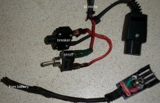
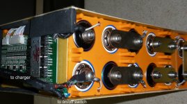
I'm guessing that the advice I was given (using a 24V unite motor with the 36V battery pack) was maybe not the best advice to follow. I'm no electrician but on looking at the damage done P1000132.JPG it looks to me that the over driven motor created too much heat for the system wires to cope with? the thing was though it seems to have melted from the battery back to the breaker switch, (or the breaker was the first weak link in the chain?) not from the motor back, the motor leads are fine and don't seem to have had any heat stress at all. The controller seems to be intact, no signs of any damage inside. The battery is still showing 40V coming from the burned out leads P1000131.JPG and I'm hoping the BMS is still OK but not sure how to determine that? I'm in the process of ordering a 36V Currie motor to replace this one, I'm hoping that was the main reason for the burnout. I used 10amp cable on all the connections but not sure if I need to get higher rated cable, the original battery cable looks the same as what I've used, but, it may have been first to meltdown from the looks of the damage?

If anyone out there has a more accurate diagnosis on what may have happened to cause this from looking at the photos I'm open for suggestions. Thanks for all the advice to date, without having forums like this, us novices out here would be left with our collective pants down and empty bank accounts from expensive trial and error experiments. It's good to know there are guys out there to help out when we're up to our necks in quicksand and no vine or Tarzan in sight to get us out!!

Regards
Hiconic
 
dnmun said:
what is 10A cable? do you mean 10AWG? you need to get rid of those connectors and switches too.

10Amp gauge wire (cable) is what I bought from Jaycar (Australia) The breaker and switch are definitely being tossed out as they are fried! I will need to replace the wires from the battery, (obviously) as they also are fried but need to check exactly how I should go about this without damaging the BMS (if it isn't already cactus!). Could anyone give me steps to take to safeguard damage when soldering, do I need to somehow isolate the power source from the cells to BMS before attempting to replace wires? Do I need to also beef up the wires to a heavier gauge (even though I won't be using the 24V motor again) to avoid a repeat of this situation? better to be safe then sorry. Also can anyone identify the cell brand by looking at the photos? are they in fact Headways or another type? Thanks in advance.

Regards
Hiconic
 
We would also need to see your setup and the controller demands the amps from your battery and the battery gives it and the motor takes it. So they should match the battery and bms. loss the switches.
 
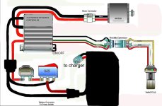
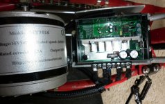
Here's some details on my set-up Chopper wiring.jpg you can look at the previous photos of fried wiring to see where they fit into the scheme. This is the controller set up 24V350W motor.JPG disregard the info on the motor label.

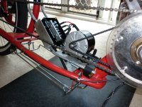
I'm not sure of the amp draw on the battery/motor/controller as I've not been able to measure accurately with the knowledge I possess on electronics. I know how to get a reading on the voltage from the battery using a multimeter, but to get a reading of amp draw while the motor is under full strain (when I'm on the bike!) and without a cycle analyst is beyond my abilities. Here's what the set-up on the bike without the battery attached underneath looks like, P1000134.JPG. and this is the bike all in one piece. P1000107 - Copy.JPG

The battery voltage when fully charged is around 41V I need to get a bit of a tutorial on how to do an accurate reading of amp draw on battery, cell voltage, and how to set up an on-board meter (other than cycle analyst) that shows amp current draw, remaining amp hours left in battery...etc. I have that small meter that I've used in my charging set up but I couldn't work out how to use it for a monitor on the bike in motion. I have to go to work but let me know what else might be helpful to tell you about the set up and I'll post more when I come home tonight. Thanks and sorry about my limited knowledge, I'm always willing to have a go at things just to test myself and see if I can pull it off, this bike has been in my head waiting to come out for a very long time so I want to at least try to get it right.

Well I'm back in from work and got some info from the website about the motor, this was all they had on the Unite 24V 350W

No-load currency/A ≤2.0/1.4
No-load rate speed /rpm 3450
Rating Torque/N•m 1.22
Rating speed /rpm 2750
Rating currency/A ≤18.7/12.5
Efficiency/% ≥78

Motion Dynamics Controller specifications
12V-48V Input Voltage (Battery Bank) 12V-55V (Regulated Power Supply ONLY!)
•High Quality Aluminium casing!
• 0-100% Speed Regulation!
• Constant torque with Pulse Width Modulation (PWM)
• High Quality Industrial Design
• Efficient High Voltage Regulator
• On/Off Switch (Built in!)
• 3 Soft start settings (Off, Slow, Slower) ramps up to the desired speed once the controller is switched on, and unlike cheap controllers every time you switch it off and on (using the switch) it will ramp up to speed again!
• Max Current up to 100A* (25A model burst rate = 50A and 50A model burst rate = 100A for SHORT periods)
•25A or 50A Continuous duty
•2 Oz Double Sided PCB
• High Speed Mosfet driver averaging 1.6uS opening/closing times
• High Current 180A Mosfets with worlds lowest RDS On in TO-220!
• Low Battery Voltage cut-out (for 12V, 24V and 36V)
• Adjustable Frequency From 300Hz to 1.5Khz

Hope this helps to establish a clearer view of the set up, battery is as mentioned in previous post a 36V - 12 AH LiFepo4 from BMS batteries.

Regards
Hiconic
 
Anyone have anything to suggest? I'll take any help on a fix for this . My first concern is to replace the battery wires from the BMS and the last cell post. Need to find out what I should do to avoid damage to the BMS when soldering a new lead, also the correct gauge wire, as the original (as you can see in the photo above) turned into a ball of what looked like solder on the bottom of the battery box. The problem is that the heavier the gauge the harder to solder onto the BMS.

I really would appreciate help on any part of this problem as I'm stuck with the fear of causing more damage to the system, and that means more money (that I don't have!!) to outlay. Thanks in advance for the shared knowledge.

Regards
Hiconic
 
If you cut open the pack you can find the bms and thsense wires that put into it. Or just leave on the charger and let the bms balance the pack over time.
If you open it up put some sense wires and plug for monitoring later. This is a bms battery pack made up of headway cells ?
 
999zip999 said:
If you cut open the pack you can find the bms and the sense wires that put into it. Or just leave on the charger and let the bms balance the pack over time.
If you open it up put some sense wires and plug for monitoring later. This is a bms battery pack made up of headway cells ?

Hi 999zip999

If you look at the post above you will see that I've already opened the pack(see battery photo) as my system had a meltdown. I've found the leads that attach to the BMS and as I've said, I need to replace wires that have been fried (see photo) and probably a good idea to replace the ones that didn't fry just to be sure no damage remains in the system. My problem is how to approach doing the soldering onto the BMS. I don't want to fry any of the components on the board and need to know if I have to disconnect any leads from the circuit board (maybe the ones that connect all the cells to the board??) P1000135.JPG any ideas would be greatly appreciated. Oh and yes it's a BMS battery with what I think are Headway cells. As I now have access to the BMS and the cells how do I go about measuring the individual cell voltages?

Regards
Hiconic
 
What I think I see in the pics, is a fairly small motor pulling way too high a gear. This is what causes the huge amp spike, that melted the motor and wiring.

You gotta get that motor turning, or it melts itself running in an rpm that turns 80% of the power straight into heat.

Use that low gear in the back, till you get moving.
 
dogman said:
What I think I see in the pics, is a fairly small motor pulling way too high a gear. This is what causes the huge amp spike, that melted the motor and wiring.

You gotta get that motor turning, or it melts itself running in an rpm that turns 80% of the power straight into heat.

Use that low gear in the back, till you get moving.

It's a 350 W 24 V motor running with the 36 V battery. I don't twist the throttle until I'm already pedaling at around 15 mph (I've got an old 70's Dragster speedo) and the sprocket set up I have was basically taken from builds I've seen on you tube videos. Those guys seem to have had it sorted out and had had their bikes running for some time. Not sure which low gear in the back you're talking about? The rear wheel is a internal 3 speed Nexus hub.
 
those sense wires are soldered to the end of each cell in the series. the very first wire on the left closest to the mosfets is the wire that is soldered to the bottom of #1.

so to measure cell voltage you measure the voltage between each adjacent pin on that sense wire plug where it is soldered to the pcb.

first cell is measured by putting the black probe on the first wire, and the red probe on the second pin, so that #1 is between the two probes.

use the 20V DC scale on your meter. keep track of the numbers since it will help you follow the battery pack health.
 
I have read thru the posts and think dogman is right with the motor burning itself out. Here are the controller specs that matter in this case:
• Max Current up to 100A* (25A model burst rate = 50A and 50A model burst rate = 100A for SHORT periods)
•25A or 50A Continuous duty
If the controller gives anywhere between the minimum 25A to 100A, your 10Amp wires will melt, no question about it. What I think dogman was saying is that if the motor is geared for high speed (over 20mph), when you start from standstill the motor will pull lots of amps, probably as mush as the controller is able to give and it can give up to 100A. What makes a wire capable of xAmps is how much losses it can dissipate; at 100Amps you have 100x as much losses as @10A (losses go up with the square of current) so you see why the wires would melt. Likely the BMS limits somewhat the max current, but it's likely over 10A. My advice would be that when you buy wires, don't believe ratings, but demand the actual copper diameter of the wire (some give it in inches, mm, or AWG in the US, but it gives a sense of how much current can pass safely) as well as the voltage insulation class, how many volts can it contain.
To measure current you need a current probe obviously, which are expensive and require either you to modify the electric circuit a bit (for cheaper probes) or to get a current clamp to measure directly on the DC wires.
 
bowlofsalad said:
Your pack needs balance leads. In the future, I recommend either only buying packs that come with balance leads or requesting balance leads be added to the pack before it is shipped to you. Checking the balance of a pack is a very important thing to do I think, I check mine once in a while with a cellog. You might be able to add balance leads to your pack, but you'll certainly need to gain access to the BMS and such. I don't know how you'd do that exactly though, you might be able to simply splice the wires coming from the BMS.
I'll echo that. I had built & used my battery pack for the better part of a year before getting around to making a balance harness for my pack and adding celllogs into the equation. In retrospect, I wonder why I waited so long, as the ability to monitor individual cells at all times, during charge, and while riding, is invaluable.

I'd wait for the warranty period to run out on your pack, if there is one. And then, yea, I'd open the pack and add in a balance harness and celllogs. You may also want to add in a balance charger, as the ability of a BMS to balance a pack is over-stated.
 
dnmun said:
why do you think he needs balancing leads? he has a BMS and it already has balancing leads going to the BMS. what are you guys looking at?
Just that there continues to be a raging ES argument on the relative merits of a BMS, their failure, etc. I land on the BMS-free side of that, or rather the human BMS, which calls for active monitoring of cell health, rather than relying on a circuit board for that. I acknowledge there are two sides. There is also a middle ground, where BOTH a circuit-based and human-based BMS are applied. For that, he'd need a set of balance leads, to the cells, bypassing the BMS. With that the options open up, including adding in Celllogs.
 
I put sense wires on my Ping with bms and loved it. Some 10 ga. silicon wire, 4mm or deans connectors two 6s sense wires and ringlets. Now just unscrew and install. Careful don't twrist the heads off the headways.

"keep track of the numbers since it will help you follow the battery pack health". I agree with Dmumn and write them down..
 
drebikes said:
I have read thru the posts and think dogman is right with the motor burning itself out. Here are the controller specs that matter in this case:
• Max Current up to 100A* (25A model burst rate = 50A and 50A model burst rate = 100A for SHORT periods)
•25A or 50A Continuous duty
If the controller gives anywhere between the minimum 25A to 100A, your 10Amp wires will melt, no question about it.
Yep. What seems a little odd is that the wires melted up into the cells in the battery pack - I don't know the BMS rating, but I would have expected the pack (BMS and wiring) not to self-destruct and melt down under the rated BMS load. This seems a separate issue than the external wiring.

This seems to be the page for this controller. Unfortunately, it has no current limit adjustments so you are stuck with the full 100A on tap (unless the BMS limiting kicks in - not a good means to limit current) - this may put your motor and wiring at risk unless you are careful about the gearing and speeds. I might recommend going after a means to limit the controller current as a means to avoid mishaps.

  • You might like to contact the firm and see if there is a part (resistor) you can alter to strap that puppy down to 50-60A or whatever is appropriate for your new wiring.
  • There is another controller there that actually could provide a nice 'current throttle' capability, but they spec a 1K pot for control. To use a resistive 5K Magura throttle limited to 50A (another 5K resistor in series) the circuit would need to tolerate a 10K pot for a short wire run less than 2m. That may be possible but an email to the company would be in order.
  • Another option might be to equip the present controller with a V2 or V3 Cycle Analyst with external shunt so the current could be limited. This would require that the low side of the throttle be ground-referenced (test and/or email company).
Hiconic said:
dnmun said:
what is 10A cable? do you mean 10AWG? you need to get rid of those connectors and switches too.
10Amp gauge wire (cable) is what I bought...
This is kind of confusing terminology. 10 gauge would have handled 50A without issue. 10A is sort of meaningless. It's not really clear what gauge was used in the bike, but getting a better handle on the needed gauge will help avoid a replay. Here's one of many on-line voltage drop calculators and sizing tables that can help you choose an appropriate gauge.
 
i think he decided the wires overheated because the insulation was melted on the wires during the assembly when they soldered the battery and power leads to the BMS. i don't think his BMS can make enuff power to overheat the wires.
 
Back
Top