How to connect to any battery teminals if you don't have the specific connector? Universal Battery Connnection Solution

Joined
Sep 2, 2023
Messages
12
Location
Merseyside
Hi! I would like to know if there is a convenient standardised way to connect to the pos and neg terminals of any battery regardless of the connector type. For example, say you come out to a client to wire up their ebike. Say the battery has a connection type that you've never seen before, but you still need to proceed with connecting it straight away, so you can't wait to order in a connector.

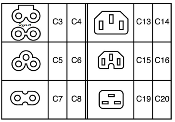
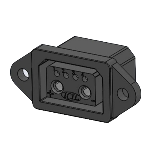
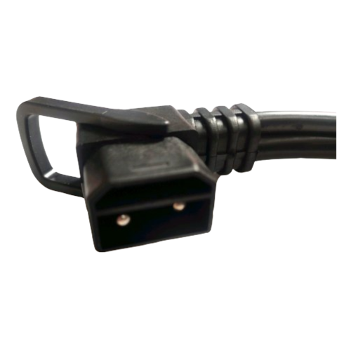
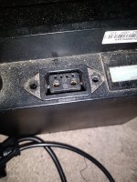
For example, here is a picture of a Greenway 48v 16amp battery. The terminals are inaccessible without a probe-style prong. Google says this is a 'USA plug'.

20231031_015922.jpg

Is there a solution where no matter what kind of battery someone has, you can easily safely and securely connect to the terminals so you can then wire up to the power wires of the controller?

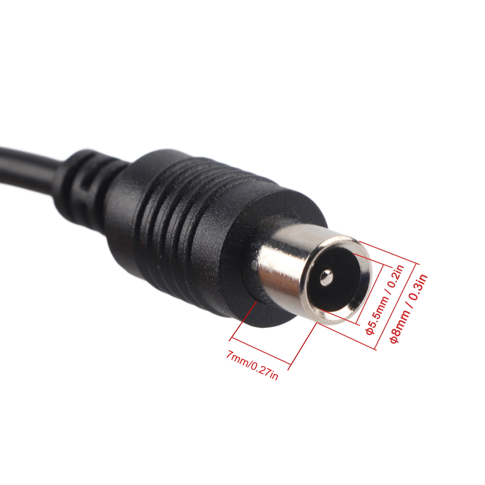
I'm imagining something like the probes that connect into a multimeter. But then there is the consideration of the appropriate size of the prongs, and how to ensure a secure and insulated connection? Maybe if there are only a few sizes, I could carry all the possible probe sizes on me, to then connect onto a wire that leads to the controller power wires? Also important is the economic factor.

Thanks for your help! I would like to conveniently and economically connect up this battery, and any other battery I come across, immediately on the spot without waiting to order a specific connector type. Is there something sort of universal that I can use?
 
There are so many possible contact sizes, shapes, designs, and depths that there's no simple safe way to do this with a small range of premade cables with contacts to carry with you.

There are many kinds of connectors, permanent and temporary, that could be used to connect in place of the original connector--but they all require cutting off the existing connectors to access the actual positive and negative wires.

One simple one that can handle reasonably high currents without melting, assumign they're correctly installed for the correct gauge wires,
They're not waterproof, and the design allows sufficient force to be able to pull the wire out of the connector under the wrong conditions.

Other connectors have different disadvantages.


There are at least two major problems that you may have with this:

Cutting off the original connector means that original parts can no longer be directly used with the system, unless you can also reinstall that connector (often not possible unless there is enough extra cable to splice it on the same way you splice on the other connector). The user is "stuck" with whatever connector you've replaced it with, to use on any future connections of these parts if replaced again.

Some systems use communications with the battery/controller to enable the system. They may rely on a specific order of connection to make this work, and the original connector will be designed to do this. If you don't do the same connection order when doing this with your own connector, the system may not work (it probably wouldn't be damaged, but that is a slim possibility too).

Some connectors are weatherproof--it's unlikely that whatever you have to field-install will be. So water intrusion and corrosion could be a future problem for the bike owner.
 
Last edited:
Can't think of a simple solution. Best I can come up with is to pre-assemble a large variety of adapter plugs that would allow you to connect X battery to Y system.

That one in your photo is certainly an oddball.
 
Hi guys

So I've been sitting and mulling this over for a couple weeks. I've realised that my query is 2-parted: firstly, how to connect this particular battery to my controller, and second, the topic of what to do if you are an ebike mechanic, and you encounter in the field an oddball battery and you need to rapidly find a solution to connect the battery to the controller, i.e. the fabled universal battery connector solution

Ok, so about my particular battery. I've found it's for the erider model 20 and the charging port type looks like the one in this picture, I've seen it referred to as 'Y-pin' and 'US plug'

CNX-24526.jpg


I've also discovered that the probes of my multimeter fit the terminals of the battery perfectly!


IMG_20231115_000325687.jpg


I would like to connect this battery to my super swanky sinewave controller here in the picture. I've had a few ideas pop into my head about various methods, can you help me narrow down my course of action?

1. Acquire another one of the Y-pin charging leads and crimp on something like an XT-60 or a junction box to connect to my controller wires

2. Use the multimeter-style probes in the battery terminals and connect those wires to the XT-60 (or alternative)

3. Probably the most crazy/dangerous idea: simply squish some thick gauge cable into the terminals, secure with sticky tape, the cable leading to the XT-60. Remove cables every time I need to put the charger in. Is there any probes or something that can do what I'm trying to get at here?

Thanks, ok so that's the first part, just what to do with my battery.

But what about the future?? 😲

Ok so, suppose you encounter an oddball, maybe a proprietary system. I'll use an example from an old thread I was reading: (Charger an prong size? Ebike)

20230805_015304.jpg

What on earth would I do if I encountered this thing?? 🤯

I think I am looking for a way to connect to ve+ and ve- on any battery. Is there such a thing as just using some sort of probe to access those parts of the battery?

But then, I'm worried about accidental shorts, especially if the battery has a connector type where the poles are very close together

Maybe I should just try to gather a comprehensive range of battery connectors and try to be prepared for any type? Is there a website where I can just buy all these different types of battery connector heads with pigtails so that I can attach my own connector to the controller such as an XT-60 or junction box?

Thanks for your help guys. This is really interesting and fun. I figure, if I can figure out how to connect up this battery, I will probably have learned a lot of skills that can help me with any battery

All input welcome!! I'm probably saying things that are making you roll your eyes haha 🤣
 
I give credence to the suggestion I've heard that some manufacturers deliberately choose connectors to prevent use with another manufacturer's system to try to lock in customers. Grin Technologies attempts to avoid this - they do select connectors they use and then provide adapters for their Satiator charger. I have researched and procured connectors to make an adapter to fit a weird 3 pin charging input socket on a battery I bought which I recall was advertised as 'ST3' but doesn't match anything else.

You may build up a collection of adapters over time as you encounter new schemes.

This is not a solution to your problems, just discussion.
 
I probably wouldn't bother with one giant junction box full of random connectors, I think it would just get clumsy and eventually you'd run out of space for adding new connectors. I'd go on AliExpress, bulk buy x60 connectors and wire. Then I'd grab some of the more common connectors and make a bunch of adapters. Yeah you might have to dig through a drawer full of adapters for the right one (a label maker is also a good idea) but I'd prefer that to a giant monster that's just going to get in the way.
 
I feel like I'm missing something, but as a (very new and humble) eBike shop owner, I think I'd create the patch cable with Andersons. Carry the 30, 45, 50, 75 Amp connectors and crimp the power leads. Use the rubber boots and maybe shrink wrap them.

Basically create the dongle on the spot.

gather a comprehensive range of battery connectors
Yes, I have quite a bin of various iterations. As it reaches a critical mass, I'll have to sort it out but for the moment I'm in the "acquiring" phase of dongle creation.
 
I think I am looking for a way to connect to ve+ and ve- on any battery. Is there such a thing as just using some sort of probe to access those parts of the battery?

Probe to test? Yes--there are various types of multimeter probes you can buy for most meters and other test equipment (usually those with banana jacks or BNC connectors) that will touch or probe into many places and spaces.

But they aren't going to carry current to use a battery on a controller.

For that, see my previous post about replacing the connectors or cutting/splicing wiring.


Maybe I should just try to gather a comprehensive range of battery connectors and try to be prepared for any type? Is there a website where I can just buy all these different types of battery connector heads with pigtails so that I can attach my own connector to the controller such as an XT-60 or junction box?
No, because there are literally thousands of different connectors used, and the same connector could be used with different wiring on various systems. (XLR is a common one for that--many use the same pinout these days, but that wasn't always the case).

You can get a number of major *charging* connectors as pigtails to the XLR over at ebikes.ca in the charger / satiator section, because the Satiator is designed with an XLR output plug, and can charge "any" battery that doesn't require communication with it's OEM charger.

However, these are not designed for connecting up to controllers and carrying the currents needed to run a motor from one.

And...most batteries have different connectors for charge and discharge ports....


You can buy just plain connectors, wires, and crimpers (for those that are contacts and shells instead of solder type), and a good high-wattage massive-tip soldering iron (preferably with temperature control, like the Weller station I use), and make adapter pigtails for things you encounter, or expect to, but you could make enough to require several large suitcases to carry around and still run into new ones now and then. ;)


And...if the connector (especially to the controller) has more than just the two main pins, it probably requires communication with the devices it connects in order to operate. It's possible the battery will operate without the communication, but likely that the controller/etc won't.

If there's only two pins, there's probably no communication and both battery and controlelr could be used on any other same-voltage/etc counterpart.


Regarding the connector you're dealing with now: that's a new one I've never seen. It's not the type that you show an image of two versions of, the common IEC AC power connector (see the wikipedia article on those for all the official variations and their purposes).
It's something that someone has designed based around that shape, probably to add features to a battery or system that originally just misused that low-current AC connector for high-current DC purposes. (very common).

If you take a good clear well-lit picture of it straight-on to it's face, you might be able to trim that down to just the connector / shell itself, and do a google image search to find similar images, which may help you find the conne ctor name and manufacturer, or at least a source for spares.

A general search for IEC AC connector brings up the usual variations, and then this search on IEC AC Battery Connector that I did on a whim
actually finds one that at least resembles yours
1700018261756.png

 
Probe to test? Yes--there are various types of multimeter probes you can buy for most meters and other test equipment (usually those with banana jacks or BNC connectors) that will touch or probe into many places and spaces.

But they aren't going to carry current to use a battery on a controller.

Nice one thanks for your reply! The one you linked looks quite similar to my one yeah. Here's a pic of the charging plug

IMG_20231115_042611967.jpg

My particular battery only has the one port I believe, like it uses the same one for both charging and discharging

For this battery, maybe I could solder some solid wire into the terminals and put an XT-60 on the end and connect it up that way? I'm just not really sure how to connect this battery's terminals to my controller! 🤔

If a battery already had power leads coming out of it I could just go the route of cutting it off and putting a more common connector type on it... Just not sure what to do for this one...

I was liking the multimeter probe idea if only it was able to accommodate the current. I thought they would have been enough cos the multimeter it came from goes to... Oh wait I just checked it it only goes to 10A 🤣 Hmm, are there any probes that can handle more?

I think I was confused because my battery doesn't have power leads which I could work on. What's the best way to access these kind of terminals that require a probe-shaped thing?

Thanks as well for mentioning about communications on battery chargers. So the XLR for example, that has 3 pins... Is the 3rd pin used for communications? And there's something special about that pin that means it won't work if I just try to connect straight to the neg and pos pins with like an alligator clip or something

Soz for rambling haha 🙃

Thank you to orcasprout, epithemuse, and offgriddownunder for your contributions too 👍

It's sounding like the usual thing to do is to just adapt a battery by installing a more common power lead connector, rather than accumulating every single possible port, right?
 
Soz for rambling haha
Yeah, soz I couldn't follow all your trailz but the connector jack you are showing on this photo:

20230805_015304-jpg.342882


What on earth would I do if I encountered this thing?? 🤯

That one sure looks like the common charger port on e-scooters, must be millions of them around by now, here is the mating plug:

61e4413d-87c5-4408-8ad2-6b2784c64a0c.a76a5208c7edacbe1db04c17b6e2608a.jpeg


From Battery Charger, Replacement Scooter Charger 42V 2A Electric Scooter Charger, 1 Set For Scooter Lovers Scooter Outdoor Professional - Walmart.com

Plug/cord is readily available online separately, if you search around.
 
My particular battery only has the one port I believe, like it uses the same one for both charging and discharging
Since that requires disconnecting the battery every time you want to charge it, tha'ts very uncommon. It risks damage to the connectors on every device on every connect/disconnect cycle, and greatly increases wear and shortens the lifespan of the connectors.

There are a few built like this, but I've only seen a couple that weren't DIY with varoius hobby connectors.


If a battery already had power leads coming out of it I could just go the route of cutting it off and putting a more common connector type on it... Just not sure what to do for this one...
Is it ever going to be used for it's original purpose? If not, you open it up and replace the connector with whatever you want to use for your new purpose that can handle the highest current the battery/etc is capable of.

If it is, then you get the right connector to use with it for your secondary purpose, or you replace connectors on both battery and it's original device (and anything else you want to use it with) so they all match, with ones that are capable of the highest current that battery is capable of.

(and then you limit the current on all the devices it will be used with so they can't overload it, by reprogramming them if they're programmable, to less than it's max capability, or risk damaging the battery from overload).


I was liking the multimeter probe idea if only it was able to accommodate the current. I thought they would have been enough cos the multimeter it came from goes to... Oh wait I just checked it it only goes to 10A Hmm, are there any probes that can handle more?

That was part of my point about that sort of thing: Meter probes aren't designed to carry much current; the devices they're used with aren't either.

There are exceptions, but they also all have different usually larger connections to also handle the higher current, much thicker wires, etc. You can look up high-current test equipment to see the various types.


Thanks as well for mentioning about communications on battery chargers. So the XLR for example, that has 3 pins... Is the 3rd pin used for communications? And there's something special about that pin that means it won't work if I just try to connect straight to the neg and pos pins with like an alligator clip or something

All depends on the specific system. You'd have to check into the system's parts you are using to find out, or just plain test them, for each case.
 
Found out a little more:

This is a moped battery! From the erider model 20. I didn't realize when I bought it off facebook, I just seen 48v 16ah battery and I got it for £80 and was like, good deal that 🤣

I was thinking about mounting it on my bicycle's rear pannier

What do you think would be a good way to connect my controller to my battery? I had an idea, can I solder an XT-60 connector's pigtails into the terminals, thereby commit to charging it through an XT-60 charging adapter?

IMG_20231116_034005007.jpg

Is it ever going to be used for it's original purpose? If not, you open it up and replace the connector with whatever you want to use for your new purpose that can handle the highest current the battery/etc is capable of.

If it is, then you get the right connector to use with it for your secondary purpose, or you replace connectors on both battery and it's original device (and anything else you want to use it with) so they all match, with ones that are capable of the highest current that battery is capable of.

I don't mind about using it on mopeds again, I just wanna see if I can make a diy ebike out of it 😝

Alternative idea: find some probes that can handle the 16ah and put an XT-60 on the probes' wires

Ooh, 3rd idea, cut off the charging port from the charger, keep that plugged in the terminals, and then put an XT-60 connector on the ends of the cables!

Side note: there's a little spark when I put cables in the terminals it's a bit scary haha

I found this old thread helpful Electric Moped (Erider Wiring Diagram Needed)
 
Found out a little more:

This is a moped battery! From the erider model 20. I didn't realize when I bought it off facebook, I just seen 48v 16ah battery and I got it for £80 and was like, good deal that
FWIW, for future consideration (to save yourself potential grief), I'd recommend thinking of any used battery (or system that comes with one) as dead, useless, and valueless, because you can't know until you personally test it whether it works, whether it is still full capacity and fully capable of delivering all the current it was rated for, or if it's worn out and incapable of running a flashlight. ;)


(also, sometimes things like this are stolen, anything that can be easily removed from a locked bike or scooter too-often is, and resold on anonymous places like the internet. Sometimes you'll find a great deal for a bike that has no charger because it was "lost"...but really the thief stole the bike and rode it till empty then is selling the thing because it's got some proprietary charger plug they can't get or is too expensive, etc...we have actually had thieves come here to sell things, or to try to get us to help them bypass locks, security codes, etc)


I was thinking about mounting it on my bicycle's rear pannier

What do you think would be a good way to connect my controller to my battery? I had an idea, can I solder an XT-60 connector's pigtails into the terminals, thereby commit to charging it through an XT-60 charging adapter?

Some thoughts before you just hook up wires and go at it:

Are those the charger terminals? Or are the other smaller pins for charging?

If for instance, the large pins are for discharge rather than charge, and you then charge it thru the discharge pins, but it has separate charging pins, there is no protection against overcharge and the potential for cell-damage and fire. :(

Same for if it only protects itself via communication with the charger. If it normally has to tell the charger to stop, then it can't tell any other charger to do so, and can't do it if it isn't wired up to the original charger exactly like it was designed to be.

Also same for if it only protects itself against overloading and overdischarge by communication with the controller on the original system.

To find out how this system works, and be safe using it outside of the original system, you'll either have to find definitive info that tells you for *this specific* battery/system (not just the brand in general, but this exact model and year etc), or you will have to open it up and see how it's BMS is setup and works.

If you prefer you can just hook up wires and hope it works without issues, and that the protections work and are setup to protect in the simplest possible way...but it's not guaranteed.

Remember: they used a custom more-expensive multipin connector on purpose. If it was really only a simple two-wire common-port common-connector BMS, they would not have done that; they'dve used the cheapest suitable two-pin connector. ;)

A typical standard BMS (not a custom-designed one like this battery probably has) just uses a set of FETs as switches to disconnect the charge port whenever any cell exceeds a certain voltage, or any other limit is exceeded during charging. Same thing for the discharge port. Most BMSes use separate ports, separate connectors for this, but there are a few that use a single common port for both, although the actual battery case usually still has separate connectors for each.


Alternative idea: find some probes that can handle the 16ah and put an XT-60 on the probes' wires
16Ah is a capacity, not a current.

You need to check your controller's current limit; that is the A (amps) current the wires and battery need to handle.

Also, you need to know how much current the battery can supply, and how much current your controller will need, to know if this battery can even run your controller.

(assuming that the battery is the right voltage for the controller).


Regading the spark you can lookup various threads on precharge for ways to deal with that.
 
information
Oh yeah I see! There are 2 holes either side of the charging port terminals, I didn't even realize those were the discharge ports 🤣 Does that mean there is a standard connector type I can get that will fit this? Is it that IEC AC one? On the male one linked in your above post, it looks like it would only go in the charging ports and not the discharge ports that are further away?

IMG_20231117_044936652.jpg

Is it possible to make my own probes? Thanks for clearing up about the difference between A and Ah, I see. I would like to get something in this kind of shape but I need something that can handle the 45A of my sinewave controller, and this is only rated for like 10 or 15A, is there anything that comes to mind I could use? Or any sort of probey thing that can carry higher amps like 50A

View attachment s-l960.webp

Could I make my own probes out of cable like this and insert into a plastic sheath like in the style of the multimeter probes?


View attachment 61rDJTxq0XL._AC_UF1000,1000_QL80_FMwebp_.webp

View attachment 51h9Rs2UgOL._AC_UF1000,1000_QL80_FMwebp_.webp

But then, how to make sure the cable doesn't fall out?

Thanks 👍
 

Attachments

  • IMG_20231117_044936652.jpg
    IMG_20231117_044936652.jpg
    4.9 MB · Views: 1
Oh yeah I see! There are 2 holes either side of the charging port terminals, I didn't even realize those were the discharge ports
I have no idea which holes you're talking about. You'll have to mark up your picture to show the specific pins you mean in each case, becuase I don't see any that would be "either side" of anything that are likely to be discharge pins (as those should be the largest pins, for the highest current, while charging pins are often smaller as they carry much less current in almost all cases).

And...as previously noted--if this is indeed the only connector on the battery, and it is used for charge *and* discharge, and those smaller pins are used for communication, it is highly likely that the two large pins are the only current-carrying pins, and that it isn't safe to use without that communication. As also previously noted, you would have to get the details on this from the manufacturer, or open it up and figure out how it works inside, *before* you just start using it. (if you just go for it, you risk cell damage that can lead to fires because it may not have any protection without the comms).


Regarding the reference of one set of pins for charging, and another for discharging....do you already know for sure which pins are the charging port terminals? If you don't, then you can't use the term to designate any pins on there, for charge or discharge, etc. It's only a guess...and guessing what stuff is what on a battery can be hazardous to your health. ;)


Does that mean there is a standard connector type I can get that will fit this? Is it that IEC AC one? On the male one linked in your above post, it looks like it would only go in the charging ports and not the discharge ports that are further away?
Pretty sure I already pointed you to the search that could find the connector, if the images/etc I found in that randomly-chosen search aren't for the actual connector. (you'll have to check them out to find out).


Is it possible to make my own probes? Thanks for clearing up about the difference between A and Ah, I see. I would like to get something in this kind of shape but I need something that can handle the 45A of my sinewave controller, and this is only rated for like 10 or 15A, is there anything that comes to mind I could use? Or any sort of probey thing that can carry higher amps like 50A
I think you need to do some research on the actual battery first, and it's capabilities, and how it actually works inside, and then on the actual connector it's using, if it turns out that it is indeed capable of running your controller and is safe to use without the original system it was designed for.
 
I have no idea which holes you're talking about. You'll have to mark up your picture to show the specific pins you mean in each case, becuase I don't see any that would be "either side" of anything that are likely to be discharge pins (as those should be the largest pins, for the highest current, while charging pins are often smaller as they carry much less current in almost all cases).


Regarding the reference of one set of pins for charging, and another for discharging....do you already know for sure which pins are the charging port terminals? If you don't, then you can't use the term to designate any pins on there, for charge or discharge, etc. It's only a guess...and guessing what stuff is what on a battery can be hazardous to your health. ;)


Pretty sure I already pointed you to the search that could find the connector, if the images/etc I found in that randomly-chosen search aren't for the actual connector. (you'll have to check them out to find out).

I think you need to do some research on the actual battery first, and it's capabilities, and how it actually works inside, and then on the actual connector it's using, if it turns out that it is indeed capable of running your controller and is safe to use without the original system it was designed for.
Nice one thanks, yeah I've already seen it working and tested when I bought it, the right port is the negative

IMG_20231117_044936652~2.jpg
 
Nice one thanks, yeah I've already seen it working and tested when I bought it,

Well, that's not relevant to what I said or what you need to know about what that connector does or how the battery works or is protected. (unless they showed you how it works, which pins do what, etc, in which case you already have all the info you need to do what you want and don't need our help ;) ).

*You* would need to find out *how* it works inside, to know if it is safe to use the way you want to use it.

If you're unwilling to do any of the work or research, it's going to be very very hard to help you, and you could easily end up with a fire.


the right port is the negative

Which "right port"? There are three pins on the right side of the connector, two on the top that are small, and one large. Then there are three matching ones on the left.

The two circled holes look like guide pin holes or mounting screw holes. They would be mounting screw holes on any other connector like that, and that's what they are on the connectors that look like these I previously pointed you to.


Are there actually electrical connections going to them, that you can see from inside the battery when it is opened up?
 
Back
Top