sl33py
10 kW
Credit to Badwolf and others who have obviously developed and done this before.
Besides Badwolf's directions on thingverse, and some detail from others here on how they did theirs - there wasn't anything consolidated in one spot. I'm a visual person and since couldn't find a step-by-step, i figured i'd build one while doing mine. Hopefully to help out the next person who wants to do this, and give back to the ES community that's helped me so much!
I had some spare time today and figured i'd give it a shot. Others might have more elegant or better steps, but these worked for me. This does involve your ability to solder and handle delicate electronics safely. If you really have no idea how to do this, i might suggest you get someone to help you.
I have my HK GT2B, and the 3dhub printed Badwolf v2 enclosure (bit rough print quality, but not horrible):
There are 8 screws on the side (and under replaceable "backstrap" replaceable grip. Cut or remove the top sticker behind antenna to split it in half).
Take your time. There are a couple other screws on the CH3 mid grip, and 3 more on the steering servo/wheel control. The antenna is super simple and just sticks up into the rubber ducky on top of the controller.
Top
Bottom
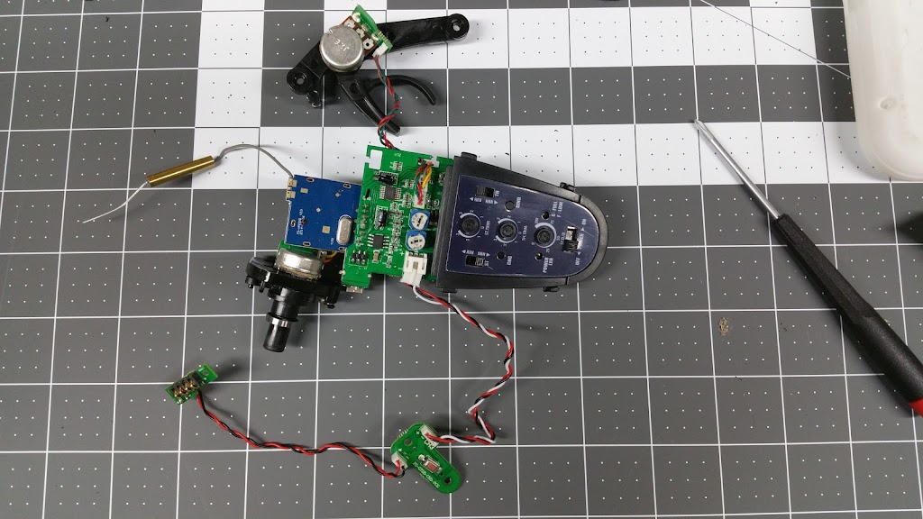
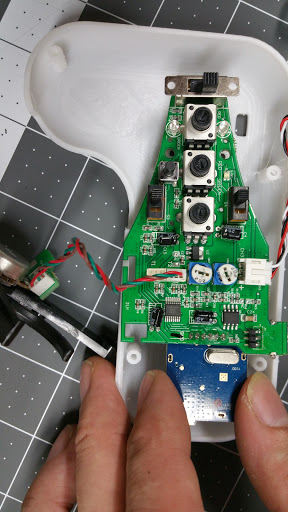
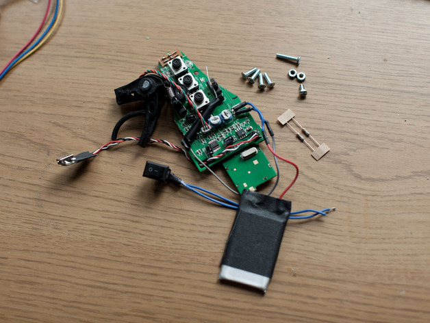
Once everything is pulled out you should have this.
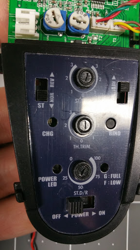
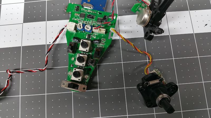
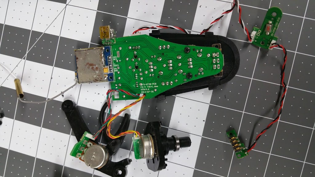
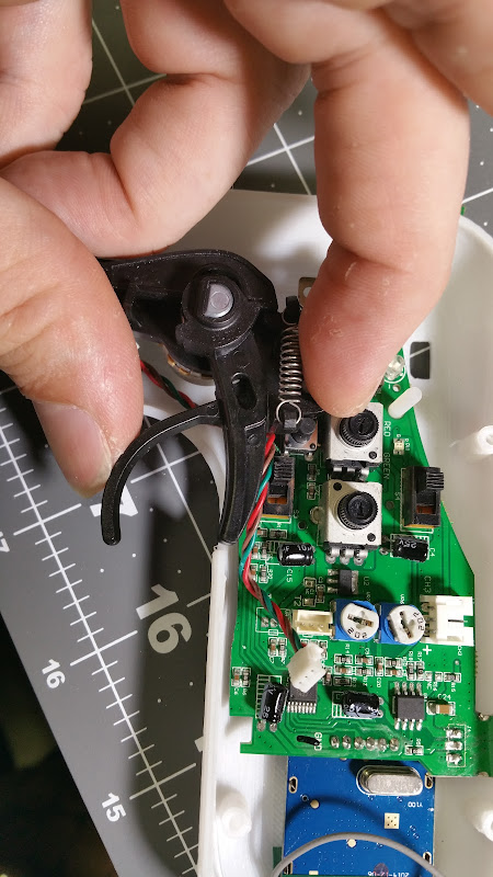
Pop the labeled cover off, and disconnect the Steering channel.
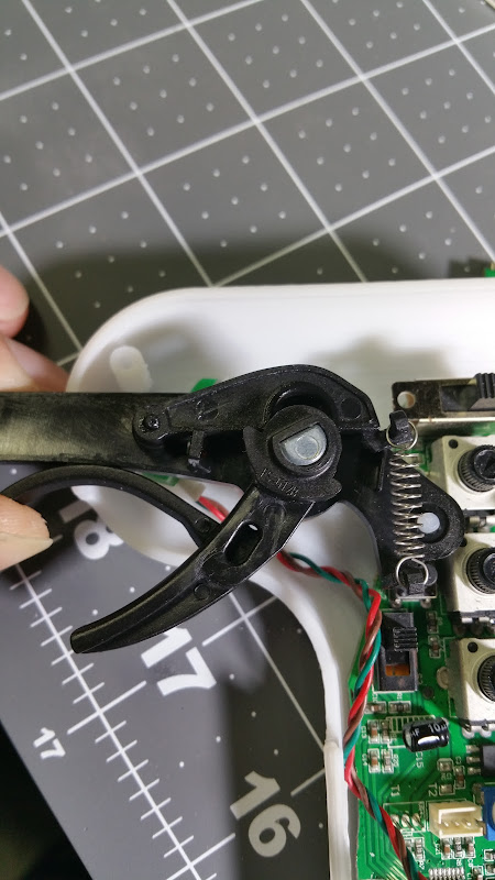
Looking at alignment and test fitting to v2 enclosure.
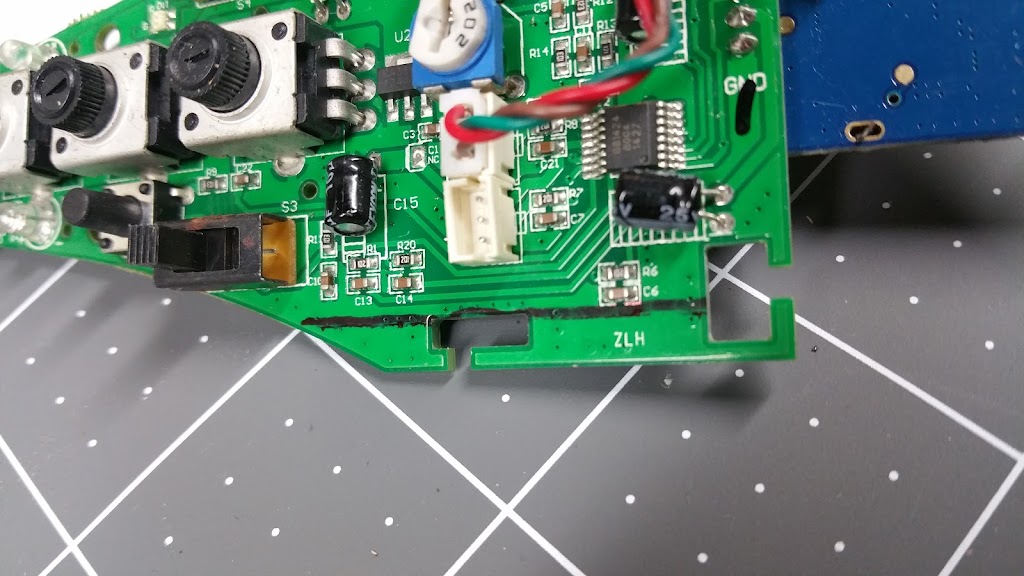
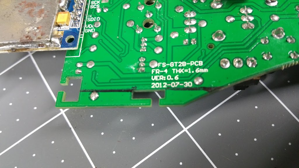
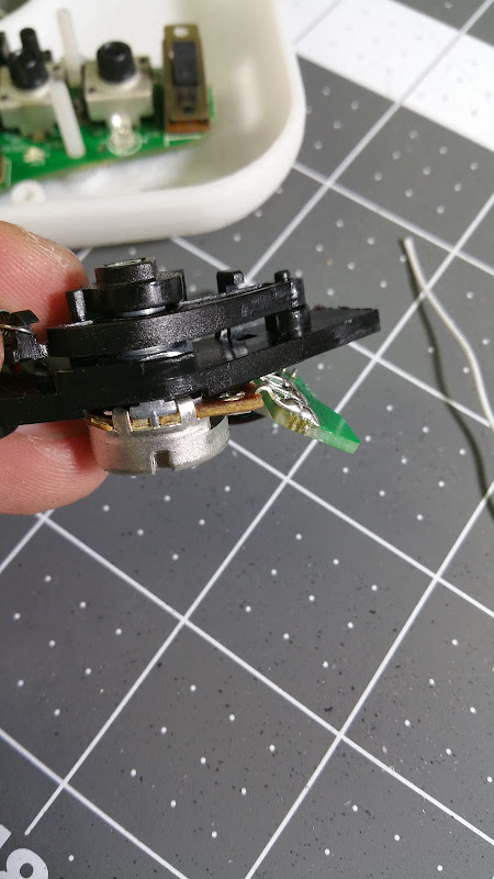
Top and Bottom of left side to remove.
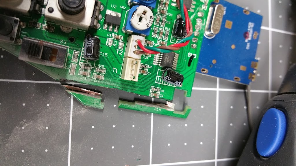
slow and steady w/ a dremel cutting disk
Let me just say that i SUCK at desoldering... couldn't find my solder wick and finally resorted to slightly more "brute force" methods.
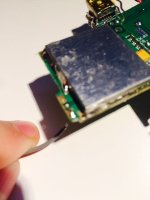
On each side of the USB Mini-B charging port there is this solder you need to remove. Desolder or...
I quickly grinded it off with the dremel cutting disk and then used my razor knife to "lift" it while heating the top and bottom solder/pins.
Time consuming and a PITA. If you have good solder wick i think you'd have this done in just a few minutes. I went slow and fiddled with it for entirely too long, but got it done eventually.
Battery steps:
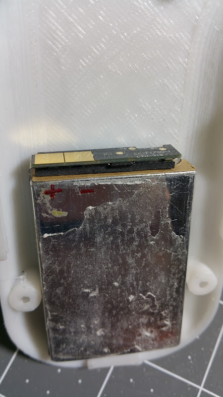
Pry/peel off the plastic and cover around the battery. I immediately made sure to label + and - , just to be extra sure i dont mix them up.
Test fit in other half of enclosure.
Waste not want not
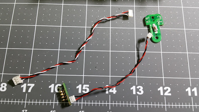
Donor wires for both the battery and relocating the USB charging port (don't throw these away).
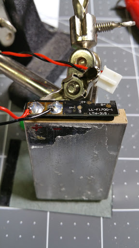
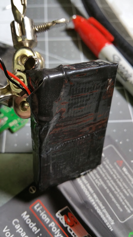
A bead of solder on the + and - terminals on the battery, notice i kept the connector for the battery to connect to the PCB. Instead of hard wiring/soldering it later i could replace it easily.
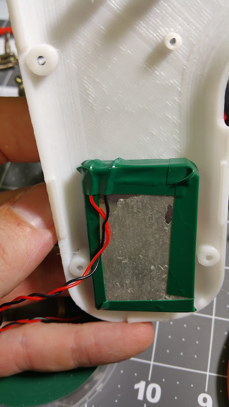
Some electrical tape around the perimeter then gorilla taped it up.
a simple loop of the antenna and electrical tape to hold it in place at the bottom.
I was going to run to the hardware store for the extra m3 screws i needed, then remembered i had this "standoff kit" from Amazon for a quadcopter KK board - perfect!
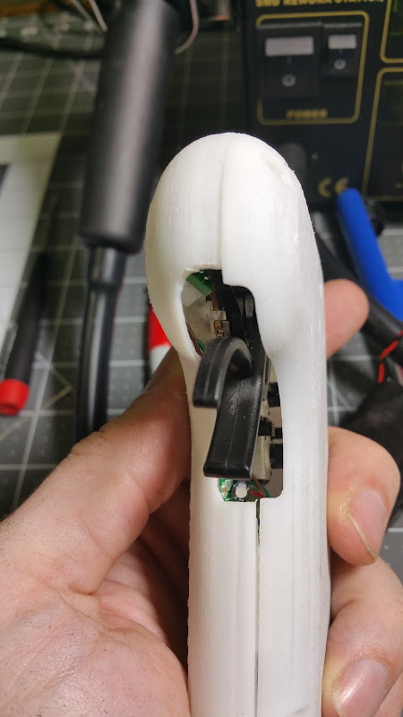
Getting close to completed. I'm not sure if it was just my print, or if all of them are going to be like this, but i found the range too restricted for full throttle to full brake on my enclosure.
I got it pretty well lined up. Notice the almost flat bar extending out from the trigger pivot. I marked it w/ a sharpie to cut and tried to keep it snug for good stability (going to be pulling/pushing on it). I also notched out the part that slides down onto the m3 bolt so it went around both the bind and one of the adjustments (throttle iirc).
Bent the backside of the throttle/trigger board to sit flat (but contact the enclosure for more support).
You can see how much i cut away to give full throttle range.
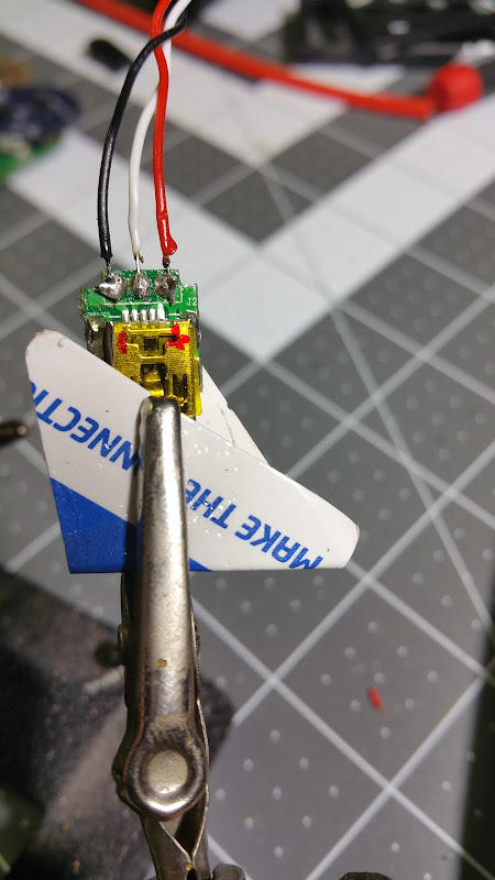
re-using the wires from the handle, the 3 wires to the USB Mini B charging port
A bit of a closeup of the battery and charging ports. Note that the USB charging port does use all 3 wires, but since i had to mangle it a bit when desoldering the port, i put the white wire in the middle to the bottom side (more room to work at the time as well). So top has black and red, with the middle white connected on the bottom. You can also see the notched out part of the throttle assembly to clear the bind button and throttle adjustment. To keep it straight (what does what), i used the label from under the top cover to help keep them ID'd.
Pretty much ready to screw it together and test. Note - use the shorter screws to hold the halves together. The longer ones i tried on the two bottom broke off part of the screw hole they went into. I used the shorter screws on the top 2, then used the longer ones on the two bottom holes. If you brake off the screw hole bottom piece - just re-use the longer screws. I've had it apart a few times already and seems to be holding up ok w/ me being careful not to try to tighten it down too much. Could be typical, or just the lower quality print (medium quality on 3dhub)...
Moment of truth:
plugged in and charging! I then got it to bind up and control my board w/o any trouble.
Some issues i had:
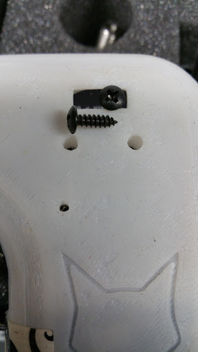
- On/Off extension did not line up for me. So i have to use a straw/keys/long-pokey-thing to turn it on.
(FIXED! - I drilled a small hole in the on/off switch and screwed in a small button head screw which gives me a flush switch on case - image below)
- Broke the bottom 2 screw holes w/ longer screws from too much force/too thin or poor quality print, or gunk in the screw hole splitting it?
- I'm an idiot. I wanted to dye the plain white PLA printed enclosure. Directions on the RIT dye say to use boiling water. Don't do that. One of the two enclosures is permanently warped. Hot tap water actually did great cleaning up the adhesive residue w/ some soap before mounting the electronics into it. seemed to also make the enclosure less "flexy" and more rigid w/o warping it. I think my hot water heater is set around 125*.
- 680 Ohm resistors - not currently used. Seems to work fine, but wanted to try it both ways. (anyone with specifics on why you need them please chime in!)
I have 100 of the 680 Ohm resistors. If anyone needs a pair for their new enclosure, just PM me. I'll ask you to send a stamped envelope so i can drop them back in the mail to you.
Bench testing this worked fine. Will try to get it out and ride it soon. Great conversion on the GT2B - now fits in my pocket!!
I hope this helps the next person trying to do this, and let me know if you have questions.
-Rob
Besides Badwolf's directions on thingverse, and some detail from others here on how they did theirs - there wasn't anything consolidated in one spot. I'm a visual person and since couldn't find a step-by-step, i figured i'd build one while doing mine. Hopefully to help out the next person who wants to do this, and give back to the ES community that's helped me so much!
I had some spare time today and figured i'd give it a shot. Others might have more elegant or better steps, but these worked for me. This does involve your ability to solder and handle delicate electronics safely. If you really have no idea how to do this, i might suggest you get someone to help you.
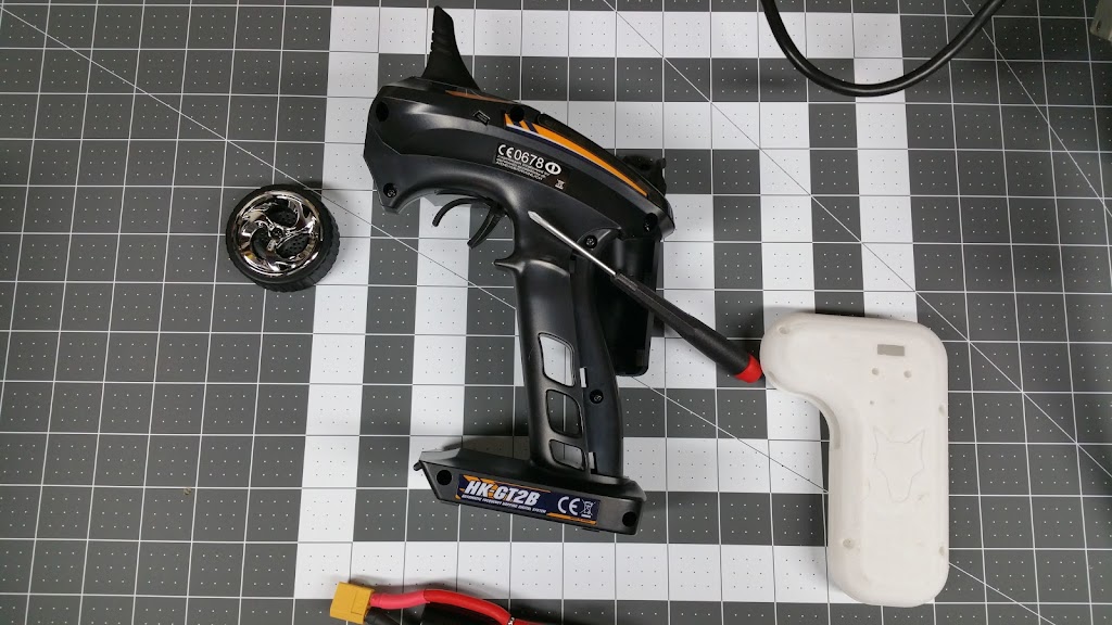
I have my HK GT2B, and the 3dhub printed Badwolf v2 enclosure (bit rough print quality, but not horrible):
There are 8 screws on the side (and under replaceable "backstrap" replaceable grip. Cut or remove the top sticker behind antenna to split it in half).
Take your time. There are a couple other screws on the CH3 mid grip, and 3 more on the steering servo/wheel control. The antenna is super simple and just sticks up into the rubber ducky on top of the controller.
Top
Bottom
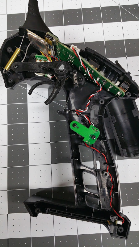
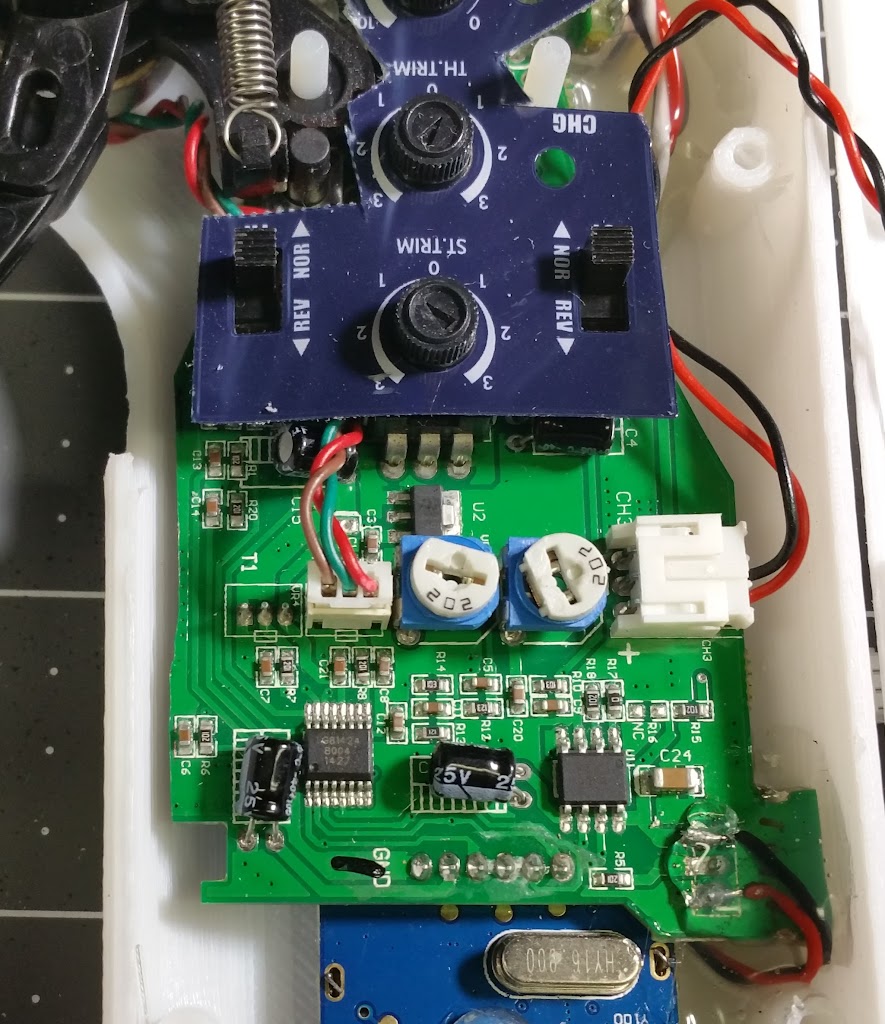
Once everything is pulled out you should have this.
Pop the labeled cover off, and disconnect the Steering channel.
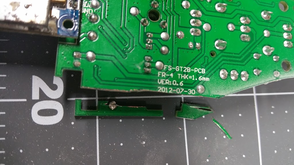
Looking at alignment and test fitting to v2 enclosure.
Top and Bottom of left side to remove.
slow and steady w/ a dremel cutting disk
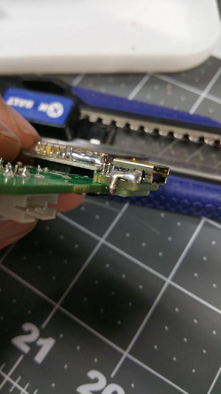
Let me just say that i SUCK at desoldering... couldn't find my solder wick and finally resorted to slightly more "brute force" methods.
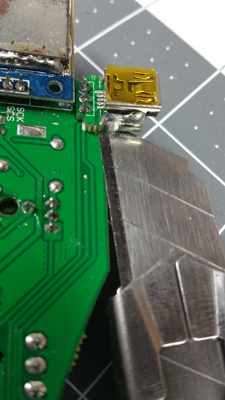
On each side of the USB Mini-B charging port there is this solder you need to remove. Desolder or...
I quickly grinded it off with the dremel cutting disk and then used my razor knife to "lift" it while heating the top and bottom solder/pins.
Time consuming and a PITA. If you have good solder wick i think you'd have this done in just a few minutes. I went slow and fiddled with it for entirely too long, but got it done eventually.
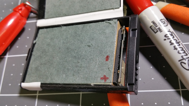
Battery steps:
Pry/peel off the plastic and cover around the battery. I immediately made sure to label + and - , just to be extra sure i dont mix them up.
Test fit in other half of enclosure.
Waste not want not
Donor wires for both the battery and relocating the USB charging port (don't throw these away).
A bead of solder on the + and - terminals on the battery, notice i kept the connector for the battery to connect to the PCB. Instead of hard wiring/soldering it later i could replace it easily.
Some electrical tape around the perimeter then gorilla taped it up.
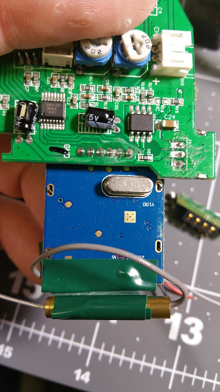
a simple loop of the antenna and electrical tape to hold it in place at the bottom.
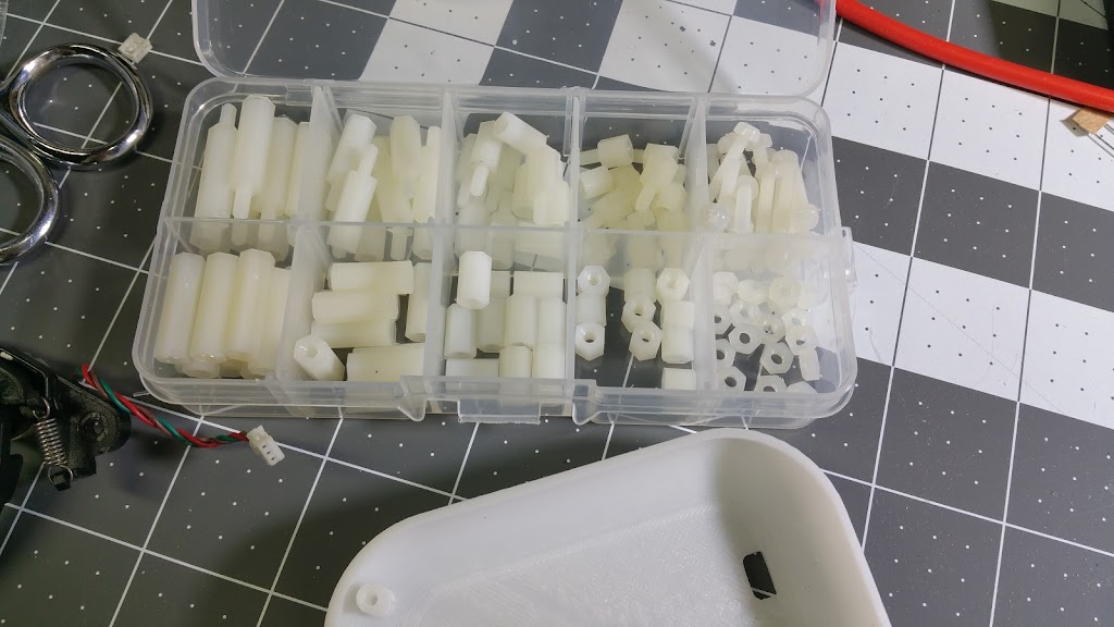
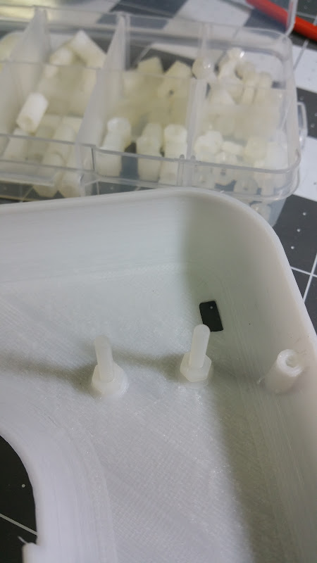
I was going to run to the hardware store for the extra m3 screws i needed, then remembered i had this "standoff kit" from Amazon for a quadcopter KK board - perfect!
Getting close to completed. I'm not sure if it was just my print, or if all of them are going to be like this, but i found the range too restricted for full throttle to full brake on my enclosure.
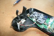
I got it pretty well lined up. Notice the almost flat bar extending out from the trigger pivot. I marked it w/ a sharpie to cut and tried to keep it snug for good stability (going to be pulling/pushing on it). I also notched out the part that slides down onto the m3 bolt so it went around both the bind and one of the adjustments (throttle iirc).
Bent the backside of the throttle/trigger board to sit flat (but contact the enclosure for more support).
You can see how much i cut away to give full throttle range.
re-using the wires from the handle, the 3 wires to the USB Mini B charging port
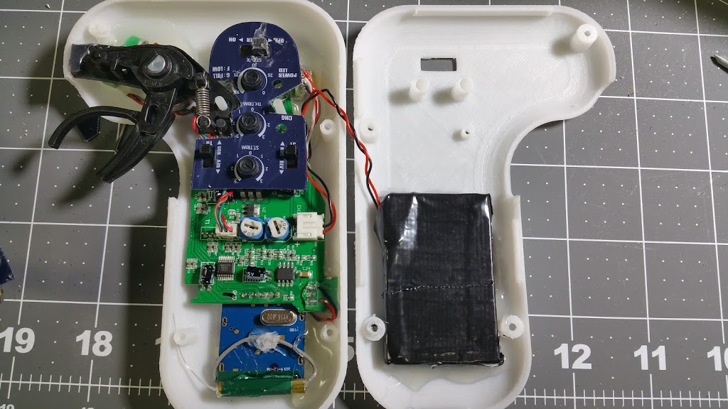
A bit of a closeup of the battery and charging ports. Note that the USB charging port does use all 3 wires, but since i had to mangle it a bit when desoldering the port, i put the white wire in the middle to the bottom side (more room to work at the time as well). So top has black and red, with the middle white connected on the bottom. You can also see the notched out part of the throttle assembly to clear the bind button and throttle adjustment. To keep it straight (what does what), i used the label from under the top cover to help keep them ID'd.
Pretty much ready to screw it together and test. Note - use the shorter screws to hold the halves together. The longer ones i tried on the two bottom broke off part of the screw hole they went into. I used the shorter screws on the top 2, then used the longer ones on the two bottom holes. If you brake off the screw hole bottom piece - just re-use the longer screws. I've had it apart a few times already and seems to be holding up ok w/ me being careful not to try to tighten it down too much. Could be typical, or just the lower quality print (medium quality on 3dhub)...
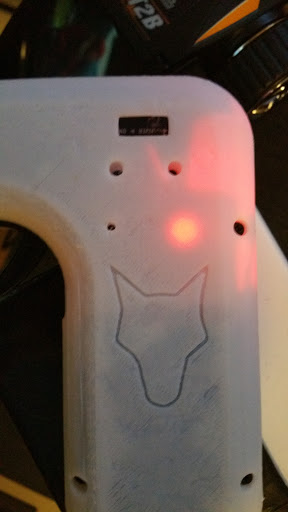
Moment of truth:
plugged in and charging! I then got it to bind up and control my board w/o any trouble.
Some issues i had:
- On/Off extension did not line up for me. So i have to use a straw/keys/long-pokey-thing to turn it on.
(FIXED! - I drilled a small hole in the on/off switch and screwed in a small button head screw which gives me a flush switch on case - image below)
- Broke the bottom 2 screw holes w/ longer screws from too much force/too thin or poor quality print, or gunk in the screw hole splitting it?
- I'm an idiot. I wanted to dye the plain white PLA printed enclosure. Directions on the RIT dye say to use boiling water. Don't do that. One of the two enclosures is permanently warped. Hot tap water actually did great cleaning up the adhesive residue w/ some soap before mounting the electronics into it. seemed to also make the enclosure less "flexy" and more rigid w/o warping it. I think my hot water heater is set around 125*.
- 680 Ohm resistors - not currently used. Seems to work fine, but wanted to try it both ways. (anyone with specifics on why you need them please chime in!)
I have 100 of the 680 Ohm resistors. If anyone needs a pair for their new enclosure, just PM me. I'll ask you to send a stamped envelope so i can drop them back in the mail to you.
Bench testing this worked fine. Will try to get it out and ride it soon. Great conversion on the GT2B - now fits in my pocket!!
I hope this helps the next person trying to do this, and let me know if you have questions.
-Rob

.jpg")
.jpg")