How to put a 60amp test load on 3.7v battery cluster

msebold

10 W
Joined
Apr 14, 2016
Messages
81
Location
Columbia, Missouri
I would love some advice on testing equipment. I am a novice. I am building an 82V 18650 battery pack that is made from 22 individual 8-cell, no-weld, parallel clusters I am constructing. The 18650 cells are NCR18650GA cells each putting out 10 amps. The 22 clusters will then be hooked up in series.

I seek to put a 60-amp test load on each 3.7 volt cluster to make sure it is working properly. Is there a reasonably priced piece of equipment on the market that would allow me to place such a test load on these 3.7 volt clusters?

Thanks in advance.
 
Take a big IGBT and do your own load.
If you have a good adjustable powersupply you can use that to adjust the load.
Good current measurement is really key though.....

something like this
http://www.ebay.com/itm/IGBT-Modul-FUJI-1MBI600PX-140-01-1400V-600A-/262961832865?hash=item3d39bf23a1:g:EoQAAOSwA29Y36dJ
is good for about 4kw of powerdissipation with correct cooling

So slap on of those on a proper heasink and follow this video:

https://youtu.be/acAuW0IVXKw

That should give you a pretty powerful load.

Regards
/Per
 
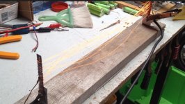
If you aren't fussed about maintaining a constant current, you can just use a basic resisive load in the form of a coil of steel wire. Take current measurements at regular short intervals so you can determine the cumulative capacity.
 
Get yourself a few hair dryers or space heaters they should work just fine with the 82VDC. Each one will draw 12A or so. You can wire them together then measure current with a clamp meter or something...
 
DVDRW said:
For 3.7V you can just use 60mOhm Copper wire underwater. Or stainless rope or stainless MIG weld wire in air.
Wire must withstand 222W
Stainless MIG wire would be ideal as it's got a higher resistivity per metre than regular steel. Try and wrap it around something ceramic though.
 
jonescg said:
If you aren't fussed about maintaining a constant current, you can just use a basic resisive load in the form of a coil of steel wire. Take current measurements at regular short intervals so you can determine the cumulative capacity.

Actually, a constant, accurate current is important to me in placing a test load on these 3.7 volt, 8-cell modules.
1. First, I want an accurate 60 amp load to mimic the maximum draw they will experience via my ebike controller (60 amps). I want to make the the copper compression contacts I am using can handle the load without getting warm.
2. Then I think I would also then like to place an 80 amp load on each cluster, which is the maximum draw these 18650 cells are rated for (10 amps per cell). If all cells are getting just a little bit warm (equally warm) it would seem to mean that all cells in the cluster are making good contact.

Again, I am a novice, and I welcome all advice from those more knowledgeable than me.

Thanks,
Mike S.
 
redilast said:
Get yourself a few hair dryers or space heaters they should work just fine with the 82VDC. Each one will draw 12A or so. You can wire them together then measure current with a clamp meter or something...

Thanks, but I need a test draw at around 4 volts, not 82 volts. Right now I seek to test each 3.7 volt module, not the completed pack in a series.
 
DVDRW said:
For 3.7V you can just use 60mOhm Copper wire underwater. Or stainless rope or stainless MIG weld wire in air.
Wire must withstand 222W

Interesting idea (to a novice like me). But where do I get 60mOhm copper wire and how do I verify that I'm placing only a 60 (or 80) amp load on the cells? Fires tend to scare me.
 
jonescg said:
DVDRW said:
For 3.7V you can just use 60mOhm Copper wire underwater. Or stainless rope or stainless MIG weld wire in air.
Wire must withstand 222W
Stainless MIG wire would be ideal as it's got a higher resistivity per metre than regular steel. Try and wrap it around something ceramic though.


I would like to know with a reasonable level of accuracy the exact load I am placing on the cells. So how do I know that the 60mOhm copper wire or the MIG welding wire is only placing a 60 (or 80) amp load on the module?
 
You'd have to use an ammeter that is as accurate as your measurement requires, in series with the load on the cell.

Note that as your cell's voltage drops the current will also drop, so you won't get any constant-current loading from a simple resistive load.

If a constant current is important to your tests, then:

You'd need something with controllable resistance to do that, and you'd need to monitor the current and change the resistance in proportion to it to keep it constant as it current drops due to voltage drop.

If you precisely measure the resistance of the load (which will change some with temperature, so keeping it at a constant temperature will let you be sure it stays at the same resistance so that calculations based on it remain constant), then you can monitor voltage instead of current, and simply calculate what the current is, and change the resistance as voltage drops to ensure the current remains constant.
 
amberwolf said:
You'd have to use an ammeter that is as accurate as your measurement requires, in series with the load on the cell.

Note that as your cell's voltage drops the current will also drop, so you won't get any constant-current loading from a simple resistive load.

If a constant current is important to your tests, then:

You'd need something with controllable resistance to do that, and you'd need to monitor the current and change the resistance in proportion to it to keep it constant as it current drops due to voltage drop.

If you precisely measure the resistance of the load (which will change some with temperature, so keeping it at a constant temperature will let you be sure it stays at the same resistance so that calculations based on it remain constant), then you can monitor voltage instead of current, and simply calculate what the current is, and change the resistance as voltage drops to ensure the current remains constant.

Okay, maybe I don't need SUCH precise load measurements. But you get what I'm trying to do, right? Put a heavy test load on each module to test the contacts? I don't want to spend a gazillion dollars on equipment. But I'm also a little leery on the idea of load testing by using a wire to short out the module. Seems just a little too imprecise and perhaps dangerous?
 
Get an rc style watt meter that will do 80amps. I think they are readily available up to 100a. Shorting a module is basically what you want in a controlled fashion. All wire/ load has resistance, you just need, well not much. In the order of 50 mohm to give you 80a at 4v. So no normal hacked device is going to suffice. But a length of wire is cheap and adjustable. I use nichrome but any old steel would probly do. It's a crap conductor so... Prefect. Just make it long enough to test and shorten to achieve desired current. Parallel if necessary. The wire will get really hot so rig it appropriately Your watt meter will tell you all you need to know.
Have fun making it glow!
 
msebold said:
pm_dawn said:
Take a big IGBT and do your own load.

Thanks. But I know just enough about electrical circuitry that the mention of an IGBT makes my teeth hurt.

OK so you are going to build your own batterypack with compression and connect to controller and motor.
BUT you are not willing to build a load ???????

Did you even look at the Video. It is not that hard.
If you have a bench supply you can skip most of the circuits in that video and just use the big IGBT brick right away,
Check this video:
https://youtu.be/7B8Q34MH3l4?t=2h2m42s

otherwise if your are willing to spend some top dollars the ichargers 40X duo series will do 70A in synchro mode.
http://www.progressiverc.com/icharger-4010duo.html

Regards
/Per
 
kdog said:
Get an rc style watt meter that will do 80amps. I think they are readily available up to 100a. Shorting a module is basically what you want in a controlled fashion. All wire/ load has resistance, you just need, well not much. In the order of 50 mohm to give you 80a at 4v. So no normal hacked device is going to suffice. But a length of wire is cheap and adjustable. I use nichrome but any old steel would probly do. It's a crap conductor so... Prefect. Just make it long enough to test and shorten to achieve desired current. Parallel if necessary. The wire will get really hot so rig it appropriately Your watt meter will tell you all you need to know.
Have fun making it glow!

Hey, thanks much for the explanation kdog, and thanks to all other for your comments. I think I get it now. Cost-effective test load achieved by controlled short and measured with watt meter. Sorry, but I gotta go now to buy a watt meter and make sure my fire extinguisher is fully charged. :)
 
I'd probly start with 1mt lengths of steel wire say aprox 2mm^2. You will need more than than one strand to handle the power- probly about 6-8. Measure the current with your watt meter. Shorten if you need more amps (but if it glowing bright red you should add another strand instead)
You'll probly end up with 6-10 strands about 20cm long at a very rough guess but you'll figure it out as you go.
 
msebold said:
redilast said:
Get yourself a few hair dryers or space heaters they should work just fine with the 82VDC. Each one will draw 12A or so. You can wire them together then measure current with a clamp meter or something...

Thanks, but I need a test draw at around 4 volts, not 82 volts. Right now I seek to test each 3.7 volt module, not the completed pack in a series.

The cluster part of your above wording threw me off and made it sound like you wanted to test groups of cells at once.

For load testing cells like this, I use an electronic load but I am limited to 30A on my load. Some more expensive units can do 60A, but those are at least $500 for a Chinese made unit.
 
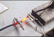
This is the poor bit of nickel I was abusing at the time.
.2mmx10mm, 85a.
Couldn't hold it at 30a, couldn't touch it at 40, smoking at 50a, dull red at 60, bright red at 85. Thought it might pop but it held in there.
 

Attachments

  • image.jpeg
    image.jpeg
    66.9 KB · Views: 1,325
Back
Top