How To Wire a 12V Brake Light and Turn Signals

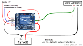
So here is my diagram of my wiring so far.
It flash with the 100b strobe controller when there is NO power to Vcc1 & Ctrl
Turn solid when there is power to Vcc1 & Ctrl

But here is the strange part.
both my 12fet controller & CAv3 has 4.97v for the ebrake line.
If I connect Vcc1 & Ctrl into either the CA or controller ebrake wires the Relay works but the clicking/switching inside is very weak.
So weak that it does not switch. I have to give it a light tap for it to switch from on or off. The little on board led lights fine when power is applied.
Now the Opto relay works fine with just a single 18650 battery which is only charged to 3.9v.
So is it because the ebrake lines is not supplying enough amp to the OPTO relay?

uc
 
Here's a revised version of your wiring diagram - this should help get things sorted...

E brakeLight_4.png
Simonvtr said:
both my 12fet controller & CAv3 has 4.97v for the ebrake line.
If I connect Vcc1 & Ctrl into either the CA or controller ebrake wires the Relay works but the clicking/switching inside is very weak. So weak that it does not switch. I have to give it a light tap for it to switch from on or off.
Sounds like you do not have Vcc1 to a +5V connection.

Try hooking Vcc1 to your +5V source and then hook CTRL to controller Ground. This should trip the relay very smartly. If it doesn't activate, leave it hooked up just as described and then measure the voltage from Vcc1 to controller ground. This should still be about 5V. If it's not, then your +5V lead is not going where it should.

  • Remember that the Vcc1 connection does not go to the CA/controller ebrake wires - it has to go to a source of real +5V --- pick it up off the controller throttle connector or off a CA throttle/AuxPot connector.

    Note that the Gnd1 connection on the opto-relay board isn't used - you can hook it up if you want, but it's not connected to anything on the board.

    The (switched) ebrake wire that reads about 5V with the brakes released goes to the CTRL input of the opto-relay and the other ebrake wire (Gnd) isn't used for this circuit - it just goes where it normally goes to the CA/controller...
Hope this helps... :D

EDIT: updated the image to show the relay contacts to make what's going on a little clearer....
 
teklektik said:
  • Note that the Gnd1 connection on the opto-relay board isn't used - you can hook it up if you want, but it's not connected to anything on the board.

    The ebrake wire that reads about 5V goes to the CTRL input of the opto-relay and the other ebrake wire (Gnd) isn't used for this circuit - it just goes where it normally goes to the CA/controller...
Hope this helps... :D

OMG no way that shit worked!!!
Blink when brake lever is released and solid when active.
Thanks so much Tek you DA MAN! :D

I want to give you a big fat kiss right now.
 
I worked on my Brake Light and Turn signal led strip over the past few days.
I cut a sheet of abs plastic as the support for the led strip.
The back of the led strip has a strip of 3M outdoor double sided tape in case the one on the led strip fails.
The other side of the abs strip is a sheet of neoprene foam sheets that I had cut channels to hide my wires.
Then another sheet of abs with 3M double sided tape in the back.

uc


uc


uc


uc


And here is a short video clip of it running on 2s lipo.

[youtube]eIxyu1d5cpk[/youtube]
 
Me too!
otherDoc
 
I can't read the circuit diagrams so pictures are the only way I can understand this.
So... to do a brake light only with no strobe I modified the pic
Also, will this optocoupler do the trick?
http://www.ebay.com.au/itm/401019721577
I am hoping to do this on a BBSHD. Has anyone with a BBSHD had a go at this?
 

Attachments

  • E brakeLight_4.png
    E brakeLight_4.png
    35.7 KB · Views: 6,263
Hey Phil-
Your circuit change is spot on but the seller claims it's HIGH-TRUE and we need LOW-TRUE.
I have sent a query to the seller for a schematic.

I have also sent a similar query for this board which looks promising: 1-Channel 12V Relay Module High and Low Level Board
With a bit of luck, answers will be along straightaway.
Will post back with results ASAP.
 
oh.. WOW - thanks very much! I will put my order on hold pronto!!

I was also wondering if anyone knew which wires were which in the BBSHD controller ... i.e. the brake cut offs and the throttle 5v supply - see image below...controller.jpg
 
phild said:
That relay module should work fine and seems to be widely available as well.
I have one that uses the exact same board but has a 10K resistor for R2, which makes it inapplicable for our use - but this version instead has a 2.2K resistor which is exactly what we need (I needed to blow up the image and compare part labeling).

The circuit for my older sample PCB is as shown below -- the new image seems to indicate exactly the same traces, part layout, etc, so:

12vRelayDriverBoard_2-2K.png
Since there seems to be some variation in these, look in the pictures for the R2 part which should be labeled "222". If so, you should be good to go.

RelayModule_Points.png

otherModule.png
If you want, you might add a note to your order and request they send you the schematic for the sake of comparison, but I'm pretty certain we are dealing with a relatively standard solution to the combined H/L trigger feature (notice the two different boards in the images in this post)

  • EDIT - this post rewritten after discovering that the board linked above differed from my old sample: new R2=2.2K (Good), old R2=10K (NG).
 
Hello teklektik

I am in awe of your build and technical skills! Just read through your build thread - AMAZING!!

The only reason I looked around for an alternative opto-coupler relay was that the ebay listing you referenced

http://www.ebay.com/itm/300776606346?_trksid=p2059210.m2749.l2649&ssPageName=STRK:MEBIDX:IT

has ended and doesn't seem to be the same item anymore - a 5v version but no 12v one.
Can you recommend a unit that would do the trick either aliexpress of ebay.com.au?
I've been a bit hasty throwing $4 at a couple of sub-optimal units - if you would be able to point me in the right direction I'd prefer to get it right!!

Thanks
 
I'm in touch with one of the vendors on eBay.Oz but we're in a short snafu because of eBay email address blocking in their message system. That driver looks promising and I'm sure the situation will get sorted shortly.

I noticed when you first posted that the part I used was no longer available - actually a couple I tested are not available just now - eBay things come and go. I'm sure a suitable replacement can be had, perhaps one from a regular micro supplier that won't suffer the vagaries of eBay retail... hang on a bit :D
 
phild said:
That one looks good too. I found a schematic for that one - looks like this:

RelayModule4_Schem_600.png
It seems that the resistor R4 is not present on the optocoupled PCBs. You can see in images where a part is missing (see empty pads at lower right corner of relay below). I'm thinking that they put that in to use as an alternative high-trigger non-optocoupled configuration to use the board for two different products...

Anyhow - same trick as the last case - leave off the H/L trigger jumper so we can run the front end with an external 5V source instead of the 12V used for the relay:

RelayModule4_wiring.png

This one is actually available from Amazon as well...
http://www.amazon.com/Channel-Trigger-Optocoupler-Module-Arduino/dp/B00Q6WQF6E/ref=sr_1_5?s=pc&ie=UTF8&qid=1459003381&sr=1-5&keywords=12V+relay+module+H%2FL

As before, requesting a schematic is a good plan, but on the face of it, this should work...
 
phild said:
I am a bit confused about the voltages - we have a 5 volt supply from the brake cut-off reed switch and we wish to drive 12 volt light. So don't we need a 5 volt relay that can handle 12 volts on the switch side?
We might run the relay off the controller +5V supply, but that would suck up 20-25ma from the controller regulated supply. The idea here is to impose as few requirements on the controller as possible. Here we use the 12V supply to run the relay and just a smidge of controller +5V current (about 4-5ma) to drive the optocoupler on the front end.

That's not to say that using a 5V relay board won't work fine and so would allow using a more conventional wiring of the pins, but if we can locate the appropriate PCBs as we have here to *not* impose this small extra load, then there is no chance that this addition could compromise controller operation. So - the 5V relay option is available if someone wants to tinker a bit, but it's not the guaranteed problem-free solution I was seeking for this thread.

  • BTW - I was scrutinizing some relay module images and realized that the one you linked in an earlier post has the same PCB but different parts than the one I have as a sample (!). Mine is NG but yours looks fine. I reworked the earlier post and put in a note about the critical resistor to look for. So - now you have two candidate modules... :D
 
Fantastic - will let you know how I get on when the unit turns up
Thank you :D

I have been researching where to pickup the brake sensors and 5v and came across Kepler's work with Cycle Analyst mods to his BBS02
https://endless-sphere.com/forums/viewtopic.php?f=28&t=60433&p=907623&hilit=Cycle+analyst+kepler#p903269

I am thinking that actually the throttle (blue) will be a variable voltage as the output from the potentiometer and I should use the red 5v controller supply (presumably this is supplying the throttle max output) and heck it is using practically nothing... does this make sense?
 
Ya - Kepler's work is always a treat - interesting projects, a great sense of form/function, and wicked good documentation. :D

Exactly - you want use a +5V supply - the controller or CA both are candidates. Don't use the variable throttle 'signal' voltage - you want the 'always at 5V' power lead instead. With a V3 the throttle normally plugs into the CA so the controller throttle connector is unused. This makes it easy to fab a mating connector and just plug it in to steal the +5V from there - no wiring hacking required. Things sort of depend on where you are going to mount the little PCB - near the controller or the CA on the bars. That's for a more generic controller - the BBSxx wiring situation is a little less flexible...

  • BTW - I ordered up a couple of those candidate relay modules and will give them a try - I don't expect any issues but might as well get things sorted since the original supplier of a 'tested' part is out of the picture.
 
Yeah I saw that one too where he finally got it going .. using the same BBS02 wiring harness wire colours for the 8 pin connector. Kepler is another very clever man! Such fun would not be possible for us dummies without you guys holding our hands...
So I now have:
BBS02-BrakeLightWiring.jpg
Assuming the BBSHD and BBS02 wiring colours are the same ... and a steady hand breaking into the umbilical cord for the BBSHD! This scares me ... although these wiring harnesses are sold as spares and not too expensive. Will need a great deal of care to extract the white and red without stuffing the others up - soldering a wire T off each and re-waterproofing the whole lot including the optocoupler.
 
Ya - wiring looks right according to the connector labels.

If I were doing that hookup, I'd probably go for 'minimum mods' to the existing wiring unless a super clean look was imperative. A Bafang compatible thumb throttle and pushbutton ebrake from EM3EV ($12 for both) could be cut down to salvage the connectors/cables and some JST connectors grafted on to get some more conventional throttle/ebrake connectors as well as one for the relay driver. That way it's easier to use other throttles/ebrakes and the LCD and motor are unmodified. If you have enough exta cable on your existing throttle/ebrakes, you might just do the same sort of thing and put a couple of mating JSTs in the run somewhere.
 
teklektik said:
Ya - wiring looks right according to the connector labels.

If I were doing that hookup, I'd probably go for 'minimum mods' to the existing wiring unless a super clean look was imperative. A Bafang compatible thumb throttle and pushbutton ebrake from EM3EV ($12 for both) could be cut down to salvage the connectors/cables and some JST connectors grafted on to get some more conventional throttle/ebrake connectors as well as one for the relay driver. That way it's easier to use other throttles/ebrakes and the LCD and motor are unmodified. If you have enough exta cable on your existing throttle/ebrakes, you might just do the same sort of thing and put a couple of mating JSTs in the run somewhere.

I want the brake light to work off either brake, I guess I could feed from both brake sensors to the opto-coupler relay ... I am using the reed switches with hydraulic disk brakes connected to each of the brake sensor cables. I am thinking that I could avoid separate connections from each ebrake sensor if I used the combined ebrake +5v or nothing single wire going down the umbilical cord. I was just going to make a shallow vertical incision, to pull out the white brake sensor wire and the red +5v supply - try to strip a small section of insulation off each - without cutting the wires, solder a wire on to each of them and hook these directly to the optocoupler relay. Then feed as much of the wire back into the insulation as possible and tape up!! A bit ugly by your standards but this will be hidden under the frame hopefully. I've got one of those small GT power meter boxes from a dead power meter that I could press into service to contain/waterproof the optocoupler relay with the wire off to the brake light, + and - 12v supply in from the DC/DC convertor and brake sensor wire and 5v in. It is going to be a bit of a challenge to avoid a birds nest of wiring!!
 
Back
Top