Add DC/DC Converter with Brake Light signal to Super73 Z Miami SE

Meyersrl

1 µW
Joined
Mar 19, 2024
Messages
4
Location
US
Im looking to add a headlight and tailight (with brake signal) to my super73 z miami. This may be more of an electrical question but here it goes.

My current thought is that I can use the extra green 5 pin connector coming out of the controller. This would go into a 48v/12v dc converter. This alone if it works should allow the tailight and headlight function assuming the light functionality of pressing the ^ arrow on the control pad would enable 48v output through the connector.

Now for the working brakelight. If one of the 5 pins is the brake signal could I use that to trigger an spst relay that enable an extra 12v wire going to the high input of the led brakelight?

For reference FortyCustoms has an adapter that does exactly this and I could probably just buy it. However Im relatively handy and currently they are on backorder.

https://fortycustoms.com/shop.html#!/Forty-Customs-ZX-Z-Miami-Series-Light-Module/p/577296552
 
How much current do the lights take, worst case?

How much current can the proposed connector output, continuously?

If the first is more than the second, it's better to use a dedicated connection to your battery for the DC-DC input, with it's own fuse to protect the battery and wiring against DC-DC/etc failures.


If the second is more than the first, then you can use the proposed conector (assuming that it can output the voltage you need).


Most of the 5-pin cables I've seen on controllers are for a display, and do have a battery-level wire from the controller in it, but it's usually very thin, as it only has to handle *just* enough current to power the display and the controller brain's LVPS (taht makes the 12v/5v/etc that powers the controller internals other than FETs (which are powered by the main thick battery wires). There's also usually a ground wire (also very thin) and two data lines to talk to the display, and a "lock" wire that has to be connected to the battery wire to turn the controller on. (that's usually done inside the display by a tiny transistor that can barely handle the few dozen mA current for the controller LVPS itself, and sometimes not even that).


The brakelight can be triggered by a relay, but most controllers don't put those signals in common cables, they usually have separate cables to the brake levers for this, which typically have a 5v pullup on the signal pin, and a ground wire. The levers are usually simple switches that just short those two together. If the relay is a 5v type, then you can do a modification of the lever wiring to use it reliably. First, disconnect the signal wire of the brake lever from the controller, and put the coil in series with the brake switch signal wire and controller 5v (sourced from the throttle wiring, etc, if there isn't 5v source at the brake connector *other than the signal wire*), and when the lever is pulled it turns the relay coil on.

The relay usually has both NC and NO contacts, and the NO ones are not connected until the relay is powered. The NC are connected when the relay is off, and are not normally used for this setup. The brake light gets it's power wire connected to whatever power source it needs, and the ground wire to the NO contact. The common contact goes to the power source ground (not the controller ground at the brake lever, though these can be the same point the current may interfere with controller operation).

If you need the ebrake function as well, then you can add a second relay*** wired identically for the coil, parallel to the first one, but use the NO and common contacts for the ebrake signal and ground wires from the controller.

***it's better if you can use a two pole (2P or DP) relay instead of two separate ones, so the coil current required is lower and stresses the controller less).

If you're using the relay for ebrake signal anyway, you can instead use the 12v from the lighting power instead of the controller 5v to power the relay thru the switch, and use 12v-coil relay instead of 5v.

There are other ways to do all this, too; Teklektik has some good posts about this in his Yuba Mundo build thread, and a separate thread for Wiring 12v brake and turn signals / etc.
 
Thank you very much for the detailed response!

I don't have all the details yet as Im getting the bike in about a week (I however currently own an RX Mojave). The issue is that the bike Im buying is the Z Miami SE edition which unfortunately does not come ready for lights. What I do know is that my RX Mojave does have lights and roughly it works through integration to the controller with a dc step down converter 48v to 12v. Super73 won't sell me the converter so Im essentially hoping to use their same methodology and hope it works on the new bike in a similar way.

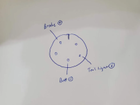
Im somewhat following what you wrote but wanted to clarify a few things. Below is a picture from another user on a Reddit post showing what 3 of the 5 pins are currently doing. Unfortunately I don't know the voltage and would have to wait till I get the bike to test with a multimeter.

Based on the below picture I believe the controller is outputing signal for both tailight and brakelight function. The led brakelight should come with 3 wires (High, Low and Negative). What Im struggling with and why I thought the relay would work is how to pass the brake signal to the led but step it down to 12v. The tailight would be always on once activated by the controller and I thought that would pass straight to the dc converter. I believe the brake light only works if the lights are turned on so I thought the relay would activate a second wire from the + side of the dc converter to the high input wire of the brake light. Just can't quite wrap my mind around how to get the brake signal to the light.

I guess the real question is what voltage are the brake and taillight pins outputting?

1710901601103.png
 
Last edited:
Im somewhat following what you wrote but wanted to clarify a few things. Below is a picture from another user on a Reddit post showing what 3 of the 5 pins are currently doing. Unfortunately I don't know the voltage and would have to wait till I get the bike to test with a multimeter.
Sounds like they're probably using a display-type "higo" (or whatever brand) connector to connect their lighting; these usually have pretty thin wires in them, and very small pins, intended for very low currents. If the bike maker (or controller maker) don't state the current capability of that connector, you'd have to check what the current input max of the DC-DC used on their bikes that come with lighting is, and not exceed that, to be safe. It's label should have this on it; if not, actual current could be measured under worst-case lighting load, otherwise you have to just guess.

(it's not just the connector and wires, it's whatever internal switches, electronics, traces, and hopefully fuses (not everybody uses them) are in the controller (or wherever that connector goes to), that limit what you can draw from it safely).


Based on the below picture I believe the controller is outputing signal for both tailight and brakelight function. The led brakelight should come with 3 wires (High, Low and Negative). What Im struggling with and why I thought the relay would work is how to pass the brake signal to the led but step it down to 12v.

The relay for the brakelight will have to be setup for however your specific light works. That you will have to check it's manual, or test it with a plain power source.

Most independently-housed DOT LED lights I've worked with are setup with a common power (automotive 12v, which is really about 13-14v or more). Then the tail has a ground wire to activate it, and hte brake has a separate ground to activate it.

Some of them are setup the other way--common ground, separate +V to activate. (I think this is how the trailer lights on the back of my SB Cruiser are wired, but it's been several years so I don't recal for sure).

Either way, most of them actually use the same LEDs on both, with diodes between the two sources so you get no feedback into one from teh other if separately activated, and more diodes in series (or a power resistor) with teh tail so it's dimmer, and brightens when the brake input effectively shorts across those to put higher voltage (and more current) to the LEDs.

The incandescent ones almost always use a separate bulb or separate filament in a single bulb, with separate wires for each but common ground.

In all the above cases, the brake light and tail light can be activated completely independently--one input is not required for the other to work.


Some use electronics to activate everything internally, and the inputs are just signals--the tail is always powered if the electronics are powered, and the brake only activates if the signal is active (either +V or ground, however they decided to design it). So these aren't independent, and the brake won't work if the tail isn't powered. The turn signal light strips I use on SB Cruiser are built this way (though they're not brake signals, just turn, same idea).


Once you know which way your light is wired, *and* what your brake signal output from the connector does, we can work out what you'd have to do to activate your specific light.
 
Looks like the converter is most likely 48v/12v 120w. Does this mean the current draw on the 48v side is 2.5amps? If so it looks like the HiGo connector could possibly handle that. Seems like the mini plugs can handle between 2-3 amps
 
If the 120w is max output power, the max input power will be higher by some amount (call it 20-25% or more) depending on load.

If it's actually 12.00v (vs automotive 12v levels) then that's 10A on the output side under max possible load. To figure the input side, you'd multiply the output W by the efficiency loss guess, so say 120w x 1.25 = 150w input power. The battery voltage will change from full down to empty, so the current drawn to support that power will also change, increasing as the battery drops in voltage. So at the lowest voltage of say, 42v, 150w / 42v = about 3.6A on the input side.

If the 120w is the max input power, then the current is less.

If the output load is less, the input current is less, though will never be zero because even with nothing connected to it the DC-DC will still have some minimum operating current draw.

But even at max current, based on above guesses, it's probable that the typical Higo wiring could handle it. If they used really thin wires or there's poor contact at the pins, it might get warm (maybe overly so). So the rest of the limitations are what stuff exists inside the controller that feed the wires on the cable, and what those parts can handle. If they use tiny transistors like those in the typical display for switching the power, they probably can't handle that much load.


How much current (or power) do your lights draw at the 12v they'll be provided by this DC-DC, when they are all on at the same time? That will help you guesstimate the power the DC-DC will draw from the controller.
 
The max wattage of any lights I’ve looked at is 45w for the headlight and way less for the taillight. But even at 90w still relatively low.

The super73 dc controller appears to be something custom as it has the "Green" input plug but multiple outputs including a circuit that turns on from the controller enabling the tailight+ (Which runs the headlight and tailight) as well as a circuit that is enabled from the brake+ pin that goes out to the brake input of the tailight. The headlight I want is standard on off, the tailight is either 3 pin or 5 pin depending on if I want to add the blinker/turn indicator function. For the simplicity of this Im really just trying to figure out the best way to enable a 12v circuit using the brake+ from the controller but using single dc converter.

To start it looks like the tailight+ and batt- would be the inputs to the 48v/12v dc controller. This would enable 12v power when the lights were enabled from the switch on the handlebar.

I would need to split the output from the 12v+ where one goes the tailight+ and the 12v negative to tailight-. What is the best methodology to switch the circuit of the 2nd 12v+ line based on the Brakelight+ coming out of the controller? Would a MOSFET work vs a relay?

What I really need to find out is what's the voltage of the taillight and brake light pins. If they are 5v output then they could trigger a MOSFET I believe.
 
Last edited:
The max wattage of any lights I’ve looked at is 45w for the headlight and way less for the taillight. But even at 90w still relatively low.
If the 90w is at "12v" then the current is 90 / 12 = 7.5A. Half that for 45w. Etc. If the device is constant power, internally regulated, then the higher the voltage input the lower the current draw will be. If it is not, then the higher the voltage the higher the current draw will be and the higher the wattage consumed by the device. (most things are the latter)

If it's a literal 12v dc-dc, then it will be 12.0v output.

If it's an automotive 12v, it should be about 13.6v output.

If it's something else...you'd have to measure it. It probably doesn't say, so this is safest.

If the lights you're using are DOT 12v devices, then they almost certainly are rated for anything from around 10v to 15v input, and if not internally constant-power-regulated will be brighter the higher the voltage is, and dimmer the lower it is.

If they're unspecified, they're probably resistively-current-limited (if even that) and get brighter and hotter the higher the voltage, so the closer to "12v" they are the more likely they are to operate as designed/advertised.

The super73 dc controller appears to be something custom as it has the "Green" input plug but multiple outputs including a circuit that turns on from the controller enabling the tailight+ (Which runs the headlight and tailight) as well as a circuit that is enabled from the brake+ pin that goes out to the brake input of the tailight. The headlight I want is standard on off, the tailight is either 3 pin or 5 pin depending on if I want to add the blinker/turn indicator function. For the simplicity of this Im really just trying to figure out the best way to enable a 12v circuit using the brake+ from the controller but using single dc converter.

Once you know what the actual signals are from the green plug, then we can work out the wiring and parts needed.

If all your lighting runs from 12v DC-DC converter, then essentially the signals from the plug will just power relay coils. The relays themselves will then switch the 12v on/off to the various lights.

If the headlight and taillight will be always on if hte bike is on, no relay or control signal is needed for htem. They are simply wired directly to the 12v DC-DC converter output, and the DC-DC's input is wired directly to the switched side of the bike battery, so they turn on as soon as the battery is on.

If the H&T will only be on under specific conditions, then if you list those conditions we can figure out what hardware and wiring is needed to make that happen. For instance:

To start it looks like the tailight+ and batt- would be the inputs to the 48v/12v dc controller. This would enable 12v power when the lights were enabled from the switch on the handlebar.
Is this switch connected to anything right now? If so, what exactly is it wired to, with what voltage, and what current limit does it have? What happens when the switch is on vs off? (does it ground a connection, or supply power to it? Is it a momentary switch, or latching? Does it switch from one electrical connection to a different one, or just make or break a single one? Etc.).


I would need to split the output from the 12v+ where one goes the tailight+ and the 12v negative to tailight-.
There's no need to "split" the output into + and -, because it already is (if it wasn't, you couldn't run anything from it as there is no way to get current flow).

If you mean something else, you might need to draw it up, or better describe it.

What is the best methodology to switch the circuit of the 2nd 12v+ line based on the Brakelight+ coming out of the controller? Would a MOSFET work vs a relay?

Depending on the available signals from your control source (green plug), I would just use an actual relay. A FET switch may require other parts to ensure the gate is always correctly driven, doesn't spike and blow the gate, heatsink for the FET depending on it's resistance and the current flow thru it and airflow past it, etc. A relay just needs a reverse-biased diode across it's coil so it doesn't cause problems with whatever signal drives it, and sufficient current to make the coil pull in the contacts.

There are also modules available with solid state switches, relays, FETs, etc., each with different control signal options, and different output switching options, and ways to connect the wires to them. There's almost certainly one that will do what you want once we know what that is. :)


What I really need to find out is what's the voltage of the taillight and brake light pins. If they are 5v output then they could trigger a MOSFET I believe.
If the FET is designed for 5v signal switching, yes, but there are other considerations as noted above. Some FETs are made with logic-level gates, many are not and require specific amounts of gate drive signal to operate them as switches (vs amplifiers).
 
Back
Top