How-to wire a CA-DP plug to Crystalyte Sensorless Controller

justin_le

Administrator
Staff member
Joined
May 28, 2007
Messages
2,310
Location
Vancouver
Hey, so we got a sample of the crystalyte sensorless controllers some time ago so that we could tell Kenny how to make them CA-DP compatible if people request this. Here are the basic details for anyone who wants to attempt the mod themselves. The only tricky bit is the throttle-override wiring.

Part 1, Shunt resistor:

The shunt on the sample controller we got (48V 25A unit) had a 2.1 mOhm resistance, not sure how much spread there is from board to board but it's usually around +- 15% or so, and hence individual calibration is always required. The white S+ wire goes to the mosfet side of the shunt, while the blue S- lead goes to the ground side.

The black ground wire of the CA can be connected to either end. If you attach it to the S+ side as shown in the photo here, then any current flowing through the CA power leads such as from a Cycle Lumenator light powered from the CA will also flow through the shunt resistor and show up as current on the CA display. If instead you wire the black ground return to the ground side of the shunt, then you won't see the current draw from headlights and other accessories that tap into the CA for power. If all you want is the CA to measure your motor energy consumption and not the accessories, then this would be the preferred wiring arrangement.
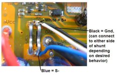
Shunt Wire.jpg

Part 2, Power:

The red power lead to the CA should be attached to the spare pad where the Vcc-L label shows on the board. This is the battery voltage after the ON/OFF switch, and by wiring the V+ lead here you ensure that the Cycle Analyst shuts down when the controller switch is turned off.
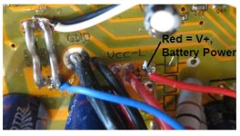
Battery Power.jpg

Part 3, Speed:

Part of the appeal of the CA-DP installation is that it picks up the motor speed information from the motor hall signals rather than requiring an external spoke sensor and magnet. However, in a sensorless controller there aren't any hall signals as such. With the previous incarnation of the analog Crystalyte pedal first controllers, there was still a signal line that would toggle at each commutation and could serve as a speedo pulse, but it was prone to glitching at startup and causing false speed readings in the 100's of mph.

On these new boards, there is an LM339 comparator chip that compares the motor phase voltages to a synthesized neutral voltage and the three outputs are conveniently brought out as 3 test point pads on the ciruitboard, so you can trivially solder the yellow CA-DP wire into one of these to get the motor speed reading. From my testing the pulses are very stable even at low speeds (3-4 mph) and during startup:
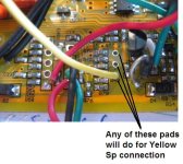
Speedo Connection.jpg
 
Part 4, Throttle Over-ride

The last detail is only important if you want the CA to be able to over-ride the throttle in order to impose a custom current limit, speed limit, or low voltage cutout.

The throttle wiring is the same as the other infineon style boards. The throttle signal comes into a pad labelled Sp, flows through a 2.2K resistor R8, with a filter cap C8, and then is directed to an input pin on the microprocessor. The hall throttles used by ebikes are are able to source a significant amount of current, so for the CA to pull down a throttle signal it has to do this _after_ the 2.2K series resistor, and this sometimes ends up being a bit of a hack.

View attachment 2

Fortunately, the signal here goes through another resistor R36 (3.3K) to an unused pad labelled SLA on the circuitboard. By replacing this resistor R36 with a surface mount diode, then the SLA pad becomes the perfect location for soldering the green throttle over-ride wire.

View attachment 1

And here is what it looks like on the actual board, original circuit:
Stock THrottle WIring.jpg

And with the diode modification for the CA throttle over-ride wire:
Modded Throttle Wiring.jpg

If you don't have access to any surface mount diodes, then the easiest thing to do would be just short out R36 with a straight jumper, and wire an inline diode to the SLA pad and solder the green wire to the other end of that.

Justin
 
Justin,

Can you point me to other threads where you show how to install the CA-DP pigtail for other controllers? I have several 12 fet controllers I would like to update.

Thanks,

Dave
 
Hi Dave, if you open up your controller you'll probably find that it's basically the same as what's pictured above, only you'd tap into one of the hall signals for the speedo rather than the output of the back-emf comparator. I've probably looked at a half dozen of these chinese digital control boards and all had the same component designator naming scheme and basic throttle circuitry as illustrated. The components could be moved around in relative location but look at the designators (R36, R8 etc.) and see if they are in the right location to match the throttle signal.

The shunt, Gnd, and V+ points are always trivial to figure out.

-Justin

dbaker said:
Justin,

Can you point me to other threads where you show how to install the CA-DP pigtail for other controllers? I have several 12 fet controllers I would like to update.
Thanks,

Dave
 
I would like to confirm that new production of Crystalyte sensorless controller WILL NOT work CA-DP.

We received the first production Crystalyte sensorless controller back in Oct/Nov 2010. All without CA-DP plug, we recently open it up and hook up with the CA-DP wire, as per Justin's instruction, it works. When we received the new controller in Mar 2011. We ordered with CA-DP connection, we plug the CA in, it is getting reverse amp. We open it up, one of the wire is connected to the data port. Our guess this is for the latest Crystalyte e-display, which is another version of CycleAnlayst. We re-wire the connection to the shunt+ and -, we manage to the amp reading. However, when we try to get signal from the hall. There are no signal come out. I have another tech guy to review if we missed something. There are absolutely no hall signal, which mean you can't get RPM, if you can't get RPM, you can't get the speed, if you can't get the speed, you can't limited the speed. So either it is running out of room to store addition code, or it was done in purpose. At this time, I haven't able to get a clear answer from Crystalyte. The only alternative that I can see here is to use CycleAnlayst direct plug with speedometer.

If you have the recent Crystalyte sensorless controller, most likely you cannot use the CycleAnlayst direct plug.

Ken
 
What Ken says is mostly correct. Crystalyte has been contracting/developing their own display device which they are now calling a APM meter (for Advanced Power Management) that isn't yet formally released pending some enclosure retooling. It is fundamentally different in implementation from the CA, using a commutation bus to the controller's microchip to get pertinent info rather than tapping into analog signal lines like the CA.

Unfortunately in the price sheets Crysatlyte sent out to dealers for their 2011 motor and controller series, they called this device a "crystalyte cycle analyst" and hence the motor controllers were advertized as having a "cycle analyst" port on them. I politely let Kenny at Clyte know that it's not cool to use the CA name on a different and unrelated device so hopefully this confusion will be cleared. Crystalyte does now have the info to do an actual Cycle Analyst connector on their controllers for any dealers who request that, but buyers should be aware that any of these controllers available at the moment are almost certainly wired for the APM meter (which is NOT NOT NOT a "version" of the Cycle Analyst).

-Justin

itselectric said:
I would like to confirm that new production of Crystalyte sensorless controller WILL NOT work CA-DP.
We received the first production Crystalyte sensorless controller back in Oct/Nov 2010. All without CA-DP plug, we recently open it up and hook up with the CA-DP wire, as per Justin's instruction, it works. When we received the new controller in Mar 2011. We ordered with CA-DP connection, we plug the CA in, it is getting reverse amp. We open it up, one of the wire is connected to the data port. Our guess this is for the latest Crystalyte e-display, which is another version of CycleAnlayst. We re-wire the connection to the shunt+ and -, we manage to the amp reading. However, when we try to get signal from the hall. There are no signal come out. I have another tech guy to review if we missed something. There are absolutely no hall signal, which mean you can't get RPM, if you can't get RPM, you can't get the speed, if you can't get the speed, you can't limited the speed. So either it is running out of room to store addition code, or it was done in purpose. At this time, I haven't able to get a clear answer from Crystalyte. The only alternative that I can see here is to use CycleAnlayst direct plug with speedometer.

If you have the recent Crystalyte sensorless controller, most likely you cannot use the CycleAnlayst direct plug.

Ken
 
justin_le said:
What Ken says is mostly correct. Crystalyte has been contracting/developing their own display device which they are now calling a APM meter (for Advanced Power Management) that isn't yet formally released pending some enclosure retooling.

Crystalyte does now have the info to do an actual Cycle Analyst connector on their controllers for any dealers who request that, but buyers should be aware that any of these controllers available at the moment are almost certainly wired for the APM meter (which is NOT NOT NOT a "version" of the Cycle Analyst).

-Justin
Justin,

I don't know when you communicated with Crystalyte, my communication with Kenny was dated 2 days ago, April 15, 2011. He stated he is still "waiting for Justin's instruction". The problem is NOT knowing how to wire the CA into the controller (we know how to wire it), or request from Crystalyte which we did. It is the controller were built purposely without any hall analog signal. Without it, the C.A. will not able obtain speed information, no matter how you wire it. Perhaps, I can send you one of new batch sensorless controller (ordered with C.A. plug-in), you can examine it if you able to get hall signal or RPM signal from it? Or if there is another way to get speed information else where from the controller?

I wanted to have C.A. plug-in!!!! I am your supporter!
I DON'T want any new Crystalyte display or APM, whatever they call it.

Ken
 
i don't think it is confusion. it is blatant trademark infringement and if he sells or distributes in the US with that info in his marketing materials you have every right to file damage claims in US district courts.

this is not cool and kenny should learn that none of us appreciate what he has done and it will impact his ability to sell C'lyte equipment, worldwide.
 
itselectric said:
It is the controller were built purposely without any hall analog signal. Without it, the C.A. will not able obtain speed information, no matter how you wire it. Perhaps, I can send you one of new batch sensorless controller (ordered with C.A. plug-in), you can examine it if you able to get hall signal or RPM signal from it? Or if there is another way to get speed information else where from the controller?
That's what the first post in this thread describes, as far as I understand it:

Part 3, Speed:

Part of the appeal of the CA-DP installation is that it picks up the motor speed information from the motor hall signals rather than requiring an external spoke sensor and magnet. However, in a sensorless controller there aren't any hall signals as such. With the previous incarnation of the analog Crystalyte pedal first controllers, there was still a signal line that would toggle at each commutation and could serve as a speedo pulse, but it was prone to glitching at startup and causing false speed readings in the 100's of mph.

On these new boards, there is an LM339 comparator chip that compares the motor phase voltages to a synthesized neutral voltage and the three outputs are conveniently brought out as 3 test point pads on the ciruitboard, so you can trivially solder the yellow CA-DP wire into one of these to get the motor speed reading. From my testing the pulses are very stable even at low speeds (3-4 mph) and during startup:
file.php
 
amberwolf:

1.) I know how to wire the CA-DP
2.) I have followed the instruction from above
3.) I have successful to make it work on the first batch of sensorless controller.
4.) I have successful wire another brand of sensorless controller without any problem

It is the second batch of Crystalyte sensorless controller that will not work, because there is no hall signal come out (R49 pad). If you can't get the hall signal, you can't measure rpm, then you can't measure the speed. Question had already sent to Crystalyte why they have disable the hall signal. So far no answer reply on this.

Ken
 
Sorry to hijack this thread. My sensorless controller also has the pads to install hall wires. I recently bought a sensorless controller from Lyen that have the same pads. I installed hall wires and Im able to run it sensored. Have you tried running these controller with hall sensors. Have you tried running this controller sensorless with 9C motors and does it shudder under high amp loads.
 
itselectric said:
It is the second batch of Crystalyte sensorless controller that will not work, because there is no hall signal come out (R49 pad). If you can't get the hall signal, you can't measure rpm, then you can't measure the speed. Question had already sent to Crystalyte why they have disable the hall signal. So far no answer reply on this.
Ah, I misunderstood; sorry. :(

So there is no LM339 on there at all? (or other chip that takes the phases' back-EMF and converts it into position signals?)
 
icecube57 said:
Sorry to hijack this thread. My sensorless controller also has the pads to install hall wires. I recently bought a sensorless controller from Lyen that have the same pads. I installed hall wires and Im able to run it sensored. Have you tried running these controller with hall sensors. Have you tried running this controller sensorless with 9C motors and does it shudder under high amp loads.
The Crystalyte sensorless controller run very smooth, i got it as fast as 63km/h at 72v, and ran out of road for the speed. I have tried differ type of motors, they all work well. I have never tried 9c motor, but i have tried keywin sensorless controller. It had a jerky start. As a result, i never use keywin sensorless on daily use ebike. The Crystalyte sensorless use Crypress chip, it is somewhat differ to compare.

Ken
 
amberwolf said:
itselectric said:
It is the second batch of Crystalyte sensorless controller that will not work, because there is no hall signal come out (R49 pad). If you can't get the hall signal, you can't measure rpm, then you can't measure the speed. Question had already sent to Crystalyte why they have disable the hall signal. So far no answer reply on this.
Ah, I misunderstood; sorry. :(

So there is no LM339 on there at all? (or other chip that takes the phases' back-EMF and converts it into position signals?)
That is the sad part. Yes, i have look for alternative signal. I have another tech guy to put the controller on scope to see if we missed anything. The hall signal was disabled by the factory. For what reason, we don't know.

Ken
 
itselectric said:
amberwolf said:
So there is no LM339 on there at all? (or other chip that takes the phases' back-EMF and converts it into position signals?)
That is the sad part. Yes, i have look for alternative signal. I have another tech guy to put the controller on scope to see if we missed anything. The hall signal was disabled by the factory. For what reason, we don't know.

Hi Ken, OK that is interesting and it means that Crystalyte really hasn't settled on exactly what the details are on their new 2011 catalog offerings, what with 30 and 35 mm stator widths sensors/no sensors etc.

Is it possible for you to take a close-up photograph of the 2nd set of sensorless boards that you got from Crystalyte which don't have the LM339? This would imply that the latest boards use an onchip ADC to sense the back-emf voltage and do all the sensorless back-emf timing in software rather than hardware.

Depending on how this controller drives the mosfets, it may be possible to get a suitable speed pulse from the gate drive signal to which ever (high or low) mosfet which does not do PWM. So I would suggest you have your tech guy look at that on a scope and see if there is a signal that toggles once per commutation whether or not the throttle is engaged. If there isn't anything, then indeed one would just need to use the -DPS model of Cycle Analyst.

-Justin
 
I have a friend why bought the first Crystalyte sensorless controller 72V 45A 12 4110 fets of the lastest batch Maxwell65 got and it also have problem.

This is very curious to see that crystalyte did so poor QC !!! :shock: :(

The blue and white wires for the shunt was connected to the location of the RS232 connections!!!!! :? :roll:

And the green wire from the speed signal was also connected to the RS232 pins of the controlller board!!

Originally the controller he received was just able to allow the cycle analyst to read VOLTS.. and no current, no power and no speed.

I relocated the blue and white shunt wires to the shunt but i have no clue on where to solder the speed signal wire !!! :x

Normally the pin with the label SP .. IS the location where we solder the speed signal wire
... but o that controller , the SP pin havethe throttle signal soldered on it...

To try to debug that speed signal i soldered a 1K resistor in serie with the green speed signal wire ( that goes to the cycle analyst) to avoid blowing somethig due to bad connections... and while the motor was running, i tried to connect the other lead of teh resistor to different pins location on the controller board

I had no cussed finding the speed signal... :(

WTF !!

Why crystalyte dont test their stock BEFORE to sale them !!!!

Max is a nice guy and this is not his fault but the problem is that we still are not able to read any speed on the CA-DP connector for the cycle analyst!!!

Justin or Ken,,, any info.. or update??

did someone found how to get ant speed signal on these board??

Teh picture showed above anout 3 possible pins that give the same speed siganal DONT exist on the sensorless controlelr i am tryint to repair....Plus it dont habe any diode and ant TO-92 component on the pcb.. like shown on teh picture above...

HELP! :(

Doc
 
If I had one here, what I would do is set up a 2-channel oscilloscope with one channel on the input to the gate signal for a phase, to give a reference sync signal for the second channel.

Setup the motor to run at say 50% no-load speed, off the ground, and start it running.

Then start probing the pins on the MCU until I found the same signal, and mark that to eliminate it.

Do the same with the next gate, and then the third.

Now use any of those gates as a reference on the first channel, and find the other pin(s) on the MCU that show the same pattern of signal. There should be three of them, offset from each other and the gate, and those should be the "hall" signals (created by whatever electronics is on there to sense the BEMF). Tapping any of those ought to give the speed signal for the CA. If it causes problems with the CA connected you might have to add a high-impedance buffer (like a CD4040 or similar) from it to the CA.


I'm not *certain* that this will work, but it should.


BTW, regarding the wires in the "wrong" places, I thought someone said in this or a similar thread that Crystalyte is now going to have their own version of a CA and that these new controllers are pre-wired for that, and not the regular CA. If so, then they probably go to the serial comm because their display will be just a display, with data sent to/from the MCU directly, and the MCU will do all the calculations and measurements, since it already knows what the current is from it's own shunt readings, and voltage and whatnot, so given a fast enough MCU to run the motor and to do the calcs, it could do all of what the CA does as a part of the controller, if they code it to.

Theoretically it could do a lot more, as it could also display controller diagnostics, internal controller settings, even allow user modification of settings via front panel buttons. But I don't expect they'd go that far (though I would).
 
amberwolf said:
I thought someone said in this or a similar thread that Crystalyte is now going to have their own version of a CA and that these new controllers are pre-wired for that, and not the regular CA. If so, then they probably go to the serial comm because their display will be just a display, with data sent to/from the MCU directly, and the MCU will do all the calculations and measurements, since it already knows what the current is from it's own shunt readings, and voltage and whatnot, so given a fast enough MCU to run the motor and to do the calcs, it could do all of what the CA does as a part of the controller, if they code it to.


Yes, i saw it on electricrider website:

It's the APM Display.

apmdisplay.jpg


attachment.php


Power indicator: APM-Display
Desc: Active Power Management Display - The APM-Display is a dashboard display panel that not only displays battery voltage, current, speed, etc, but it also allows the user to limit the current output. All features and details of the APM-Display will be listed separately when available.

http://www.electricrider.com/docs/APMDisplay_Owners_Manual.pdf

Bike.jpg


PDA.jpg


Doc
 
Hi all,

I got an email from one of my clients this afternoon pointing me to this thread, up until this time there were a few people who were asking me about the CA plug on the new sensorless controllers, I honestly thought it was just a matter of calibrating the shunt, but obviously it is not that simple as I read this whole thread, to this day I have never used a CA cause I always monitor everything manually, but being in the biz it looks like I will begin using one not to mention the fact it just looks really cool and its very informative. that being said when it comes to electronics I’m a moron, just don’t know all that much,,,but I do know that I’m an avid user of crystalyte products and they serve me well,,,im still using my 5303 from 2006 and the same 12 fet controller from 2007,,, and it all works perfectly to this day. Soon I will try out the sensorless motor and controllers. (I have been so busy I just have not had the time to set it up on my bike yet)

back to the CA,,,as far as I know its Justin’s invention, correct me if I’m wrong, and yes he deserves all that is his monetarily in terms of patents etc.but its up to him to enforce those patents (if there is any) as for crystalytes offering of their APM display, I have yet to hear of its availabilty,,,i will find out soon as they may still be working on getting out the bugs, correct me if I’m wrong, if it is available and if Justin has some say as to whether or not clyte has no rights to offer their own version then he may have a case against clyte,,,,but that being said I would be very surprised if he can enforce sole proprietary rights,,,if that were the case there would only be one manufacturer of cars, so no Mercedes, no Ferraris or porches, no Samsung or Panasonic and no miele or GE,,,,, :shock:

the only thing that Justin can do is to offer up the CA at competitive pricing, or start manufacturing controllers that are only compatible with his version of CA, or be sure that clyte does in fact offer true compatibility with his version of CA. Judging by crystalytes overall business practices I would not count on it,,, when I ask something of them they either totally ignore my requests and do not provide answers, or simply agree but don’t comply. For this I am sorry but there is not a whole lot I can do about them and their business practices, I can only offer what I believe to be a great product at a competitive price. In the end that is what crystalyte does and I cannot complain about that, yes the CA may not work with the sensorless controllers for the moment, but I have faith that will change, but one thing is sure when you apply throttle, Crystalytes motors perform above and beyond all expectations and that is why I will always carry their product proudly.
 
The APM does have quite a few features. I've been running mine since about April 15th and it also has user settable lvc and current limit.
APM_display_800x600edit.JPG


CrazyJerry
 
Kiwi said:
can you please give us an idea of the functions or the APM and how you are liking it.

Yes! Overall I like it. Here is my own personal pro and con list:
Pro:
- Large, easy to see.
- User settable lvc and current (amp) limit. Both settings work excellent and as advertised.
- Fairly easy to figure out access to set screens even if you don't read manual. Not intuitive is a 5 second wait where setting becomes saved each time you want to change a value in a particular screen. However, manual states this clearly.
- If you get bored while riding, there are a variety of items you can monitor (battery voltage, amps draw, **watts, trip odo, speed, efficiency displayed as percent, and even torque output).

Con:
- Large, too big to fit on the mini t-handle steer bar (just enough room for twist shifters and thumb throttle). Worked out better since the APM mounted to the interior roof.
- I'd like to be able to specifically select the three or even four parameters that I'd like to monitor on the screen. Instead, in its current form, the APM will allow you to auto scan through the various screens but taking ones eyes off the road during this round-robin is not convenient. One should only have to give a quick glance at what you want to see and not have to wait for it.
- There is a question about how accurate the speedometer is and I believe this also affects the odometer. I've hooked up an external (stand alone speedometer/odometer) so this is no longer a problem. This has also worked out better since I can dedicate the APM to display current draw and the battery voltage bar/numeric readout (ex: 55.2v)

I am somewhere up around 600-700 miles on this current build and will update if anything fails/burns/goes haywire/etc. With all of this rain we're getting I should've made the stupid thing amphibious!
CrazyJerry

Edited - **Added watts to the description
 
Back
Top