Hub motor to crank drive. Motor & Sensor chat appreciated

Joined
Oct 24, 2012
Messages
11
Howdy all. I'm glad to be a part of the forum and around like-minded folk who love experimenting, innovating and developing. There's so much about electric bikes that make them such a perfect platform to create with.

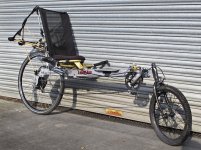
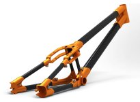
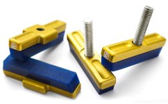
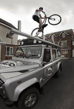
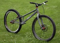
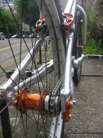
I've been a trials mountain-bike rider for about 11 years and for the last 4 years have been performing with the MAD mountain bike display team. In that time I've experimented a lot, working on custom frames, funky rims, brake pads and fluid, all sorts. (See some images at the bottom) As well as the trials riding, I now commute and tour on an old Linear Limo, which I absolutely love riding.

I'm now working on a completely custom project, and it'll be my first foray into electric bikes, other than a little bit of research whilst studying product design @ Loughborough.

Whilst the Bosch and panasonic units sound like they perform really well (the Bosch in particular), they're not going to offer me the level of design congruence I want to achieve in this project. Having looked at fwd, rwd, mid-drive, chain-drive and crank drive, it seems that combining the motor axle to the bottom bracket axle will be the cleanest (not necessarily easiest) way of adding power. As so much of this project needs to be completely designed in-house, the results will be worth the extra effort to include some interesting engineering into the equation. My task is to find a balance between creating everything from scratch vs using an off the shelf system like the Bosch. I hope with some help from you guys, we'll find a really great solution.

I'm looking at taking a compact hub motor (a 500w, 48v Cute motor look the best option to me at the moment), stripping it, mounting the hub shell as an integral part of the frame, creating a new axle for it, and mounting the cranks on the axle. The fact I will be using the FSA Metropolis Patterson crankset will add further complexity to the matter, but I'll save that discussion for a minute!

Depending who is riding, lets say the cadence will vary between 30 and 90rpm depending on who is riding. From what I've seen, most geared hub motors seem to have a torque multiplier of around 3-5, giving a working RPM range of 90/150-270/450 rpm range for the motor.

If I take a motor suited for a 28" wheel: At 15mph the wheel will be spinning at around 180rpm, so the motor would be working at 540-900rpm (3-5x torque multiplier). Is this a typical RPM figure for a hub motor working at an efficient level? This is where I'd appreciate a bit of general education from you guys - in finding something that will work efficiently at driving the axle at 30-90rpm.

The other thing to be considered is torque sensing. This project will not include a throttle, and maintaining instantaneous and relative motor power delivery with pedal power is a real priority. As this is such a custom project, there is a lot of room to include the most suited ideas.


Thanks, and I do hope this resource will be most valuable.

Mike.
 

Attachments

  • IMG_2880_s.jpg
    IMG_2880_s.jpg
    112.9 KB · Views: 4,482
  • MSingleton_3_3B.jpg
    MSingleton_3_3B.jpg
    82 KB · Views: 4,482
  • Pads_s.jpg
    Pads_s.jpg
    66.7 KB · Views: 4,482
  • phrame landy s.jpg
    phrame landy s.jpg
    96.9 KB · Views: 4,482
  • mg82653rc.jpg
    mg82653rc.jpg
    115.1 KB · Views: 4,482
  • rotationofimg0014small8ze.jpg
    rotationofimg0014small8ze.jpg
    183.6 KB · Views: 1,148
MalvernMike said:
I'm looking at taking a compact hub motor (a 500w, 48v Cute motor look the best option to me at the moment), stripping it, mounting the hub shell as an integral part of the frame, creating a new axle for it, and mounting the cranks on the axle. The fact I will be using the FSA Metropolis Patterson crankset will add further complexity to the matter, but I'll save that discussion for a minute!

Depending who is riding, lets say the cadence will vary between 30 and 90rpm depending on who is riding. From what I've seen, most geared hub motors seem to have a torque multiplier of around 3-5, giving a working RPM range of 90/150-270/450 rpm range for the motor.

If I take a motor suited for a 28" wheel: At 15mph the wheel will be spinning at around 180rpm, so the motor would be working at 540-900rpm (3-5x torque multiplier). Is this a typical RPM figure for a hub motor working at an efficient level? This is where I'd appreciate a bit of general education from you guys - in finding something that will work efficiently at driving the axle at 30-90rpm.
Hi Mike,

Nice work :D

Welcome to the Sphere!

Efficiency has more to do with torque than rpm. Leaving aside the relative impossibility of using the hub motor axle as output, without adding additional gearing between the motor and the cranks you will be dividing its already meagre power potential by a factor of 2 or 3....
 
These are the other nearest commercial equivalents to what you are proposing, Mike.

http://www.bofeili.com/cn/index.aspx

http://www.bicycle-motor.com.tw/b2.html

Ref: http://endless-sphere.com/forums/viewtopic.php?f=28&t=26995
 
First thing: Forget that 500w Q128 motor. If you do a search on this forum, you'll find that they're gutless. I have both Q100 and Q128 motors and I'd say that the Q100 gives more power.

Unless you're a very good engineer, I think you'll have problems with your fundamental idea of using the motor axle to drive the crank IIUYC because the axle is joined to the stator along with the wires. You'd need a robust slip-ring arrangement to transmit the power through the rotation.

If you're starting from scratch, you'd be better with an RC motor, but you'd have to make a suitable reduction system. If you carry on with a geared hub-motor, a 201 rpm one is about right with a 14T drive sprocket and about 42T on the crank - so that's about 3:1. I have this arrangement on one of my bikes with a 250w Bafang QSWXK5 motor and cadence is about right, but torque is not really enough. This motor has slightly more torque than the Q128 at the same currents.

You can buy a ready-made GNGebike crank-drive kit for £270 including delivery and it'll bolt straight on to your BB and away you go. The motor itself would also be a good powerplant, but still you need a reduction system.

I've tried the Bosch and Panasonic driven bikes and can tell you that the Bosch gives more torque than a 250w hub-drive motor, but not as much as the Bafang BPM, MAC, or similar 350w plus motors with 22amps or more. So, if you want as much power as the Bosch, you need a bigger heavier motor than that Q128 one.

If you want some ideas about convertinghub-motors to crank drive, there's a guy called Vauthech on http://www.pedelecforum.de/forum/forum.php who's done a lot of good stuff. You can use the search facility there and Google translate to find his stuff. Here's a picture of one of his bikes that he made from scratch out of carbon fibre:
E-Bike-int.jpg
 
Hi Mike,

The other thing to be considered is torque sensing. This project will not include a throttle, and maintaining instantaneous and relative motor power delivery with pedal power is a real priority. As this is such a custom project, there is a lot of room to include the most suited ideas.

This gives you the option to drive the right crank by the motor, like the GNG, cyclone and others, but you wont need a freewheel crank-set, which is one part less to fail, maybe it feels a bit strange when stopping, since the motor torque does not fall instantly (so you may use a freewheel crank set however). The cycle analyst V3 will do exactly what you want if you connect a thun torque sensor.

I'm looking at taking a compact hub motor (a 500w, 48v Cute motor look the best option to me at the moment), stripping it, mounting the hub shell as an integral part of the frame, creating a new axle for it, and mounting the cranks on the axle. The fact I will be using the FSA Metropolis Patterson crankset will add further complexity to the matter, but I'll save that discussion for a minute!

The cute motors would need A LOT of rework to make the axle rotate. The only motor I know which could be converted within reasonable effort are the bafangs and copies. I had this idea myself a year ago and had to learn that cute and tongxin motors are not suitable for this, even if it seems so first. But since a week a I own a bafang style motor: http://endless-sphere.com/forums/vi...+Geared+hubmotors:+BIG+list+&+details#p652141 . I don't wanna make a new axle/shaft, I wanna reuse the original one, since it's hard to pull off the stator without damaging it. Also, using slip rings is not necessary at all.

This is what you would have to do:
-cut the wire 30cm behind motor, tie out phase and hall wires (this might be a bit tricky, you can also cut, tie out and solder back together)
-cut the axle (cut between sun gear and planet carrier)
-bore both new ends on your lathe, insert 6 x 20mm brass axle and a 6x18x0.5mm brass washer ( between sun gear and planet carrier),
- > it connects the old "axle" side with the new "shaft side", acts like a bearing
-copy the backplate (with the bsa thread on it), using 5mm alloy sheet, bore it, tie the phase wires through one, press fit the fixed axle end and shorten it, bore 3 or 6 holes into the stator carrier screw it onto the new backplate (our left support)


The motor looks like you wanted, but it cannot be used yet, the tiny 6mm brass bolt wont hold up the stress induced by the chain sprocket on the "new" shaft (it has only one ball bearing yet). This is why we have to support it by an extra bearing on output side (our right support).
- lathe a 10mm bearing surface onto the knew shaft end
- install sprocket and fasten
- build a bearing carrier plate, insert bearing

Be aware that the "new" reduction ratio of the epicyclic drive is 5:1 not 4:1 since the planet carrier is now the output.
 
if you are interested, I could post a full how-to with pics. You could even do the mod without a lathe, if you have good skills using file and drill. As already said, i did not try it yet, but I already wrote a full howto. The over all work time should be about 10-14 hours. Maybe I'll buy another bafang copy and do the mod next week, since this motor is so cheap :) BTW the 24Volt version used with 36V runs faster and can be geared down for better performance/less stress for the planet gears. I heard the 36V version can cope with 15amps, so the 24V version should cope with 22.5amps, since it runs faster, since it should have thicker phase wires or run in star config. I'll compare when I get the 24V version.
 
I just checked my paypal account and saw it's still enough to buy another motor and just ordered. Took a front motor this time to compare the dimensions.

update: I just saw that the front versions wire outled of the front version is on the other side. Hopefully the seller's drawing is wrong again, like it ever was.
 
Hi spinningmagnets!
thanks for your link. But I think modding a hub motor to let it turn it's axle was never tried yet. If it already was please let us know, I already searched for something similar but did not find anything :?
 
Great! Thanks for the responses guys - really encouraging.

Miles, cheers for the Optibike patent link, always good reading. Do you have any idea whether it's a US only, or international patent? :roll: As Crossbreak mentioned - I believe a freewheel isn't needed, provided you've got a torque sensor on there, so even with the motor set to 'zero assist' (providing you've got some juice in the battery), the very least it would be doing is turning the motor over so the rider wouldn't feel its resistance..

Miles said:
without adding additional gearing between the motor and the cranks you will be dividing its already meagre power potential by a factor of 2 or 3....

I think I missed this one; do you mean one would need additional gears on top of the planetary drive system?


Crossbreak, that's some really useful info - good to know the cute motor won't be suited. I think I can visualise your plan for re-routing the wires, but if you're willing to post a visual how-to, that'd be grand. Having one of these motors would be a big help in carrying on with the development, so I'll pick up one of these right away. One of these, you recommend? Lets say I want up to 500w of power, is purchasing the 500w, 48v motor the best option? You mentioned it's a clone of the Bafang, so is this one what I should be looking at?

Does anyone know of any folk that can supply the Bafang hubs in the UK?

The thur sensors you mentioned (as seen in this pretty flash video), look fantastic. Are these distributed anywhere?

Pretty great work by Vautech. Not so sure on the super-nifty Word-Art logo :D

Thanks again for the advice so far guys.

Mike.
 
MalvernMike said:
Miles, cheers for the Optibike patent link, always good reading. Do you have any idea whether it's a US only, or international patent? :roll:
:) They have international patent coverage.

MalvernMike said:
As Crossbreak mentioned - I believe a freewheel isn't needed, provided you've got a torque sensor on there, so even with the motor set to 'zero assist' (providing you've got some juice in the battery), the very least it would be doing is turning the motor over so the rider wouldn't feel its resistance..
If having to use the motor at all times is acceptable, sure. It would be hard going if you run out of juice, though...

MalvernMike said:
Miles said:
without adding additional gearing between the motor and the cranks you will be dividing its already meagre power potential by a factor of 2 or 3....
I think I missed this one; do you mean one would need additional gears on top of the planetary drive system?
If you want to maintain the level of power the motor would have if used in even a 29" wheel, yes. You could argue that being able to reduce speed to gain torque, using the bikes variable gearing, means you don't need so much power.
 
Miles wrote:
without adding additional gearing between the motor and the cranks you will be dividing its already meagre power potential by a factor of 2 or 3....


I think I missed this one; do you mean one would need additional gears on top of the planetary drive system?

If used as a crank drive, the slowest available wind should be used, since the pedals rpm should be around 80. the slowest bafang one can buy does 201rpm@48W, Code17.http://endless-sphere.com/forums/viewtopic.php?f=3&t=35323#p515152 and http://endless-sphere.com/forums/viewtopic.php?f=3&t=35323&start=90#p608467


With new reduction: 201/5*4=161rpm, or 80@24V which just fits perfect for a crank drive. Which tells us it won't like the 500Watts you wanna put through :shock:

Edit: It has be geared faster, with an additional gear stage, as miles already proposed. I was not aware that you directly want to mount your pedals on the shaft, so my howto as to be ab different. The stator carrier has to be pulled off. The new bearing are then obsolete, you wont even need a new side plate. But I'm afraid the hubs axle could break if used as an pedal shaft, since it's not as stable as a normal pedal shaft.
 
I inspected the pedal shaft again and would highly recommend you to make a new one, based on the original one, keeping it 15mm in dia. The original axle has only 12mm dia at the disk brake side bearing. And I would not try doing downhill with that shaft ;)

When I do the my described mod, I will use it as middrive, using a chain to the cranks (giving it 2-3times the power). If I would build a coaxial crank, I would stick to the slowest motor an run it with only 250Watts, since an additional reduction set is too much work to effort. This way you still have the freewheel function, which is worth a lot if your battery fails.

Building the thun torque sensor into the hub, might be tricky, not only because of space, it could be also affected by the motor, so it should be mounted on the outside first to test it.
 
Yeah, a custom bb axle/motor shaft is definitely on the cards there..

I looked at the TMM ones a while back - from what I gather, it looks like they're only interested in working in large quantities - but I could be wrong..? The other problem I have with using a sensor such as that is that I'm planning on having a two-speed crankset (FSA Patterson Metropolis), so it would take different readings depending on which gear the cranks are in: Unless there was a sensor mounted on the shifter to tell the controller to multiply the input torque by a factor of 1.6x when in the higher gear.

The other challenge is the physical challenge of combining the crankset with the hub, but that's not beyond the limits of technicalities..


I guess the easiest thing to do would be to run a geared mid-drive motor with a TMM style sensor'd mount and mount the Patterson crankset as normal. But it would really be a great feat to have that whole package integrated. Maybe it would be worth looking at building it from the ground up rather than using the basis of a modified hub motor..

metropolis-3.jpg


P4150078.jpeg


velocomfort-herz-x-cell_02.JPG
 
Righto, this'll get interesting for sure. It makes sense to me to make the motor more like a traditional motor - that is to have the windings fixed to the motor housing , and have the magnets on the axle.

My first step is to get the crankset, measure it up, stick it into CAD (I use Pro-Engineer 5) and investigate just how much space I've got to build the motor.

Wish me luck :)
 
Worthwhile question - I'll be using an N360 at the back, and it will need more range than the hub alone can offer. I definitely don't want a derailleur and rings on the front! As far as I know, the Patterson seems to be the most compact, cleanest looking and smoothest shifting solution out there. They also come it at under £150 ($230), so they're amazing value too. The schlumpf drive is another option, but I prefer the aesthetics (and price tag!) of the Patterson.

My main focus in this design is a clean experience all around, aesthetically, mechanically and functionally. Reducing the amount engineering work to arrive at a solution is a secondary priority. If there proves to be a better solution to the Patterson, then I'll go for that.
 
You are aiming for quite high speeds?

Adding up 2 epicyclic stages, plus the one in the Patterson, plus the Nu Vinci could put the system efficiency below 50%..
 
MalvernMike said:
It makes sense to me to make the motor more like a traditional motor - that is to have the windings fixed to the motor housing , and have the magnets on the axle.
Agreed.

It would be great to incorporate the gearing within the rotor, that would mean that you could use the full width of the bottom bracket area for the motor. The topology could get a bit labyrinthine, though.... :mrgreen:
 
I want to buy a kit like this!!!!Where, where, where????

file.php
 
How about something like this?

- The rotor runs freely on the crank axle.

- The common annulus gear is fixed to the left-hand side cover.

- The primary stage sun gear connects to the rotor structure (red part).

- The primary stage planet carrier connects to the secondary stage sun gear.

- The secondary stage planet carrier connects to the crank axle.
 

Attachments

  • Sketch.jpg
    Sketch.jpg
    64.8 KB · Views: 3,981
Back
Top