Hubmotor Ventilation John's new (now old) approach

John in CR

100 TW
Joined
May 19, 2008
Messages
14,954
Location
Paradise
I finally got to put the new approach I tried on Hubmonster to the test with a mountain climb. It's a several mile route my son has shared with videos in the pics and videos section with his Clown Bike. He'll post a video of today's ride later, but to summarize I averaged 156wh/mile hitting a max speed of 59mph on what is a continuous climb other than one short dip. The upper half is the steepest with one 30% section that I stopped at the foot and accelerated up, and one stretch of over half a mile is a steady 18% grade. It's quite curvy so I was braking and accelerating repeatedly, so the load was harder than race conditions, and I hit the peak battery current of 220A after many of the curves with a minimum voltage of 74.9V, so 16.5kw pumping into the motor. In comparison, Zombiess's bike won the SoCal race consuming 88wh/mile.

The cooling effectiveness astounded me, because when we stopped at the top magnet backing ring was only 37°C and the stator couldn't have been much warmer, if at all, because there was no warm air was rising out of the exhaust holes. The covers themselves were cooler, though not quite the ambient of 22°C like the rest of the bike.

All my other ventilation attempts used perimeter exhaust holes in both covers. With Hubmonster I wanted to get more air flow through the magnetic gap due to the wide stator of 50mm. My approach was simply intake on one side, exhaust out of the other side with blades near the stator in both covers. The blades serve several purposes:
1. Ensure that the air inside the motor is spinning at full motor rpm.
2. Prevent the easiest air flow path along the smooth unobstructed side covers where it does no good by deflecting the spinning flow of air away from the cover directly at the stator where it is needed the most. This creates a more turbulent flow at the stator, and much better cooling...like blowing air into you bowl of hot soup instead of blowing across the top from the side.

Since I ride on the road at speed, this approach works fine with this large diameter motor (stator 265mm). It barely gets warm with plenty of full stop and slow speed launches, which are the hardest in terms of heat. Once I get a controller that can go to 300A, which this motor can definitely handle, if it gets warmer than I like when I go around hunting for motorcycles to embarass, I'll first add a cowling to funnel air at the intake, and if that's not enough I'll add a ring of larger intake holes for a less restrictive intake, go to 15 blades in each cover, and enlarge the exhaust holes, so I do have an upgrade path if it proves necessary at over 20kw.

Here are pics of the side covers. Note that the blades almost touch the stator. In fact, I had to open the motor twice when I first put it back together to bend some blades flatter that were rubbing against the widest point on the stator end-windings. The blades are both bolted and epoxied to prevent them from either coming loose and rattling or coming off completely and ruining the motor. The holes are angled, forward at the top of the rotation to "bite" into the air better for the left side intake holes in the thick part of the cover near the bearing, and rearward when furthest from the road for the exhaust holes at the extreme perimeter of the right side cover to minimize the outside influences on the natural centrifugal flow resulting from the air spinning inside the motor. Air has mass, so just like a ball on a string if you spin them in a circle, centrifugal force pushes them outward trying to escape their confines.
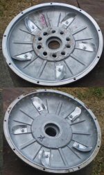
SuperV with Hubmonster inside covers.JPG

Click on the pic below and click again to enlarge to see more detail:
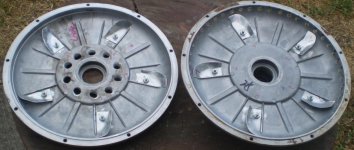
SuperV with Hubmonster inside covers large pic.JPG

The bottom line is that this approach works quite well, and even better than on the motor on my son's ebike, since his motor was warm (not hot, but markedly warm) at the magnet ring when we stopped at the top. That motor wasn't pushed into saturation either, and though it is a 200mm diameter motor, his has blades and larger holes, but with one side intake and dual side exhaust, so his doesn't get much flow at all through the magnetic gap. With much larger blades and hole, I wouldn't doubt that his flows more air, just not where it's needed the very most, so this new method is what I'm sticking with from now on. Maybe once I start doing some much slower off-road riding I'll find a need for going with active ventilation, but I'll cross that bridge when I get to it.

John
 
The fins are great. maybe fins on the outside of the intake to force air in as the air out will happen. Port and polish like an intake port. It will be hard to test to air flow thru the hub. But that hand not only tests batteries, but hub motors and controllers. Science. The problem is I don't want start looking for moster hubs. It sounds that good.
 
999zip999 said:
The fins are great. maybe fins on the outside of the intake to force air in as the air out will happen. Port and polish like an intake port. It will be hard to test to air flow thru the hub. But that hand not only tests batteries, but hub motors and controllers. Science. The problem is I don't want start looking for moster hubs. It sounds that good.

Every time I think about intake scoops the thought of all the sand and grit I get in the face at times and must be greater down near the road prevents me. I think a big V shaped stationary scoop attached to the frame and fits fairly close to the motor cover would be a bettery approach. It would be kinda big though with the small end larger than the OD of the intake holes, so it would be a big aero drag. The benefit would be to create a high pressure region of slow moving air near the intake making intake a smoother flow than a high speed air flow perpendicular to the intake. The region in front of the intake of a centrifugal fan has a huge impact on flow rate. I think sand and grit would fall harmlessly out to the bottom the scoop and out instead of getting sucked into the intake holes.

Polishing all intake and exhaust holes would absolutely make an improvement since it would reduce turbulence, which decreases flow.

I've dreamed up all kinds of rigs to create exterior blades, thus increasing the diameter of the centrifugal fan, and adding an aluminum cover with a rearward exit to complete the effect. Then you're looking at serious flow at that kind of diameter at the rpms I run. I may even try something along those lines by turning a new cover for my high efficiency motor to take it to racing performance levels. I have 2 concerns about exterior blades:
1. noise
2. Power consumption of the "fan" especially at high rpms at cruise where cooling is less necessary, because the motor is more efficient and the higher rpms already result in faster interior flow naturally. The approach I use has very little power drain, since it's just taking advantage of the already spinning air.

Until I start having heat issues, I'm not changing anything. This morning I zipped up a steep mountain road pushing a 350lb load using big power and lots of full throttle accelerations. I even stopped at the base of the couple hundred yard 30% section waiting for my son to pass at speed to see if I could overtake him before the steepest part ended. I didn't fly by until just as the grade eased up to 15-20%, but it was impressive nonetheless. Despite all that the motor wasn't even warm at the top of the climb, much less hot, so I have no reason to change anything any time soon other than figure out how to cool my controller better and crank up the power. :mrgreen:

John
 
Here's a point for discusion:
Polishing all intake and exhaust holes would absolutely make an improvement since it would reduce turbulence, which decreases flow.

Research has shown that extreamly smooth surfaces actualy "wet-out" & inhibit air flow at subsonic speeds. We learn this porting engines for maximum airflow through the ports. (definatly subsonic) keeping out big humps, abrupt direction changes & a smooth path for flow is the goal...& for maximum air flow a less than polished surface will leave a boundry layer of air on the surface & actualy flow more volume through the passage. Seen it proven many times on a flow bench in the engine shop.

The only advantage an ultra smooth (mirrored) surface finish is to reduce fouling from unburned & residuals from combustion. I advise any jr. engine builders the only place for a mirror shine inside an engine is the combustion chamber. (dome on an un-coated pistion & squishband/head)

Not that any of this applies to a hole in a less than .125"t side cover. :wink: But if you want to improove airflow through holes like that you need to provide a "velocity stack" type opening & exit to initiate & maintain a smooth flow into(and/or out of) the circular vents.
(post count increased x1)
 
Interesting stuff Thud. It makes sense to me too and is probably similar in water. I know the somewhat textured surface of water skis always felt a lot more slippery to me than those with smooth bottoms. How smooth is too smooth? I'm sure my holes could use at least a lot more tapering, so there's definitely some gain to be had working the existing holes.

The biggest weakness in execution is probably the intake area. I went as large as I dared at that radius, so another ring of holes would help reduce the flow restriction at the intake.
 
So a vortex or ventory or tapper ? OR ? Road dirt. I see a hub run that was so full of rust. Sand did grind my freewheel and bearings on the wire side.
 
I don't know if this is helpful, but here's tidbits from my "airflow experiments" in house cooling over the years. None of them have "hard data" in numeric form, as I just gauged things by feel (well, except sometimes noting how fast temperatures fell, but I don't have any of that data available anymore, as it wasnt' kept after the tests).


From what I can tell in my varied experiments with cooling my house using just the existing wind, or with fans, etc., to pull air thru the house, the only thing that really improves airflow besides providing a clear unblocked path for the air to follow is larger holes rather than smaller, for either intake or outlet.

Additionally, having outlet holes notably larger in total surface area than the inlet usually makes for increased airflow, especially if there is an external wind across the house, blowing from the side of the house with less intake area, and towards the side with greater outlet area. I assume ;) this is from a low-pressure region being created behind the house and within the side closer to the greater outlet area, and helping to pull air thru from the lesser intake side.


Regarding larger holes: If I have the front door open without the screen door in the way (also open), it has about the same total area as the front windows that open in the front room plus both bedrooms. But there is noticeably more airflow thru that single doorway than thru the combined windows, if I close the door and open just the windows, even though both are constrained to the same outlet paths. Also, adding the screen mesh into the windows or closign the screen door significantly decreases airflow.

If I have a box fan with it's grillework covers in place, it moves less air (and is a lot noisier) than one with that grillework removed. (unfortunatley I have to run any unattended fans with grillework in place because the dogs don't understand what the fan is and sometimes stick their faces in the airflow to cool off or smell things, and they could (and would) end up sticking their noses where they don't belong. :( )


Another tidbit from my days of seeking ways to reduce the number of fans in my computers, to quiet them down yet run them at highest power modes for music studio use as synthesizers and recording units, etc.: Reducing turbulence within the item you wish to cool does reduce noise, but it also reduces cooling, sometimes quite a lot. Increasing turbulence may increase noise, but it definitely increases cooling, depending on exactly how you go about it. Almost always, much much less noise is created for the amount of cooling increase than the cooling increase is "worth", so I usually went for hte most turbulence/cooling increase i could get, at the heatsinks and components themselves, usually by adding bits of copper wire wrapped around them sticking out like "hair", which also increased their active surface area. It didnt' always help a lot, but any increase in cooling without increasing the fan speed (and noise) to get more airflow was a good thing for the needs-to-be-silent studio environment.
 
Looks nice. bolts and epoxy. Didn't somebody do something like this a few years back, then the epoxy let a fin go and chopped up the windings? I recall it worked good till then.

One nitpick, maybe the nut on the outside? so you can see if it is coming off, and if so, it won't drop into your windings. You could of course epoxy or locktite the nuts, but on the outside the epoxy would be exposed to less heat.

Whatever holes in the motor you have, it's gotta improve with some kind of blower. I've thought at one time a redesign of the spokes of the stator would be cool, then realized, duhh, they don't move. But some angled fins molded into the hub cover would be nice. Then have holes by the axle and another set near the magnets.

Dirt, and particularly big rocks getting inside the hub is a real hazard where I live. I've ventilated my dirt bike motor to keep it from gathering moisture, but it won't cool it. I just did 1/8 holes along the outer edge. Too small for a big rock, but riding in mud when it happens once a year won't rust my motor.
 
dogman said:
Looks nice. bolts and epoxy. Didn't somebody do something like this a few years back, then the epoxy let a fin go and chopped up the windings? I recall it worked good till then.
El_steak did, but only the epoxy--no bolts. :(
 
There's epoxy on the thread of every bolt, so those nuts aren't going anywhere. I suggest any copies do the same.

Note that this approach isn't so much about maximizing flow. The air inside a hubbie is already spinning, so intake toward the center and exhaust toward the perimeter will result in flow. As Doc Bass proved with exhaust holes angled the wrong direction, the influence of the outside environment can stifle the flow. This is more about how I direct the flow. ie force roughly half through the air gap (centrifugal force is equal on both sides of the stator), deflect it away from the side covers directly at the stator, and not allow it out until it passes the end windings. To get that flow through the magnetic gap, the exhaust holes need to be at the extreme perimeter.
 
If you cut the bolt shorter and put a center punch dowm the center it becomes a rivet. Probaly would be eaiser to take apart. would be to tighten the bolt till it brakes. back the bolts head on the other side.
 
John This reminds me uh the time you put the cards in your spokes. We start in drapers and we end in drapers. Dogman these morning I can up with fins on the stator it took 4 mins I though of where to put the holes. But maybe all the holes on other rim as that where the heat is ? It like controling a river. But could monator with probe.
 
999zip999 said:
If you cut the bolt shorter and put a center punch dowm the center it becomes a rivet. Probaly would be eaiser to take apart. would be to tighten the bolt till it brakes. back the bolts head on the other side.

It's a permanent mod. If I had a TIG welder I'd just weld the AL blades on. This was the way I came up with to assure no rattles and no possibility I cause my own motor ruining debris. If you have a better idea, I'm all ears.

Re the 2nd post, you must be a couple ahead of me and I need to catch up to understand. I definitely won't be ready for diapers any time in the foreseeable future. :mrgreen:

John
 
Sounds brilliant!

any video? this textual porn is good, but it only makes me want for visual stimulation. :oops:
 
cal3thousand said:
Sounds brilliant!

any video? this textual porn is good, but it only makes me want for visual stimulation. :oops:

If watching the ass end of a fat guy leaving you behind badly while you record from an ebike that does 12kw peaks is your cup of tea, then yes there's video to come as soon as my son the videographer loads them up. He leaves Saturday so there's going to be videointerruptus for a while. My plan is to get a couple of Contour Roam's for the bike with one pointed rearward. For me the most impressive ebike footage is from LFP's rear facing camera for the SoCal race. At least for me, that view gives the best feel for how fast an ebike accelerates away from everything else, so I want to make some videos like that.

John
 
999zip999 said:
I saw that live everybody on the fence where shaking there heads everytime he when by. A !/4 of the time he's braking.

That was on flat ground. With enough power braking is important even going up hill. I hit 6% regen going up the mountain. Of course a lot of that was being a wuss on my part in the curves, but the extra accelerations out of every curve made more heat and a better test for the controller and the motor cooling. The motor is obviously fine, so after I move the controller to the downtube for much better outside airflow, and add a 2nd blower to the controller for greater internal air flow (and backup in case a fan goes out), then I should be able to push it safely from 220A that it's run for a week up past 270A and 20kw. :twisted:

Of course now that we went to 20ah, which pushed the top speed to 64mph due to less voltage sag, Jay is campaigning for adding a 4s booster pack for 24s to pass DoctorBass's 71mph mark. If I hit 64 on 20s, then with him aboard and 24s 75mph looks probable. 8)

John
 
Nice work ;)

Before going full watercooling (as I've seen one member do), how about adding a fuel injector - delivering water in a fine mist if the motor temperature reaches a certain threshold? Water soaks up extreme amounts of energy in the transition to gaseous phase - so the cooling effect would be very effective at 100degC. I have too many projects on my hands to try this, someone should! :D

The amount of research I've conducted makes for this "cake" recipe:
- Water pump (fuel pump) from a newer diesel engine, or from a motorcycle. Nothing huge. The ones with ceramic bearings are the ones to look for - they can pump almost any fluid if I understood it correctly.
- Microcontroller taking the temperature of the stator, and acting upon temperature.
- Dc/Dc converter able to handle the current draw by the water pump.
- Mosfet working as relay for pump.
- Mosfet for controlling the duty cycle of the injector.

If you carefully drill holes aligned with magnets/halls - you could have the pump only hitting the holes :p

I know the agni crowd have some of their motors "water misted", with good results.
 
They have electric fuel pumps that work at 12v with a adjustable in line fuel perssure guage. 3-5 psi for webers, but up to ? Maybe 15psi.
 
My motor was 37°C at the top of a monster climb that only a small % of ebikes can make, much less hauling ass with a 360lb total load. I'll leave the more complex cooling approaches to others. Should the motor start showing significant heat as I go higher than the 22hp I'm currently pushing into the motor, then I'll make the small simple changes outlined previously.

While heat is our limitation, passive ventilation has proven to be quite effective. However, most who have heat problems simply have the wrong motor for the task. Driving a motor well into saturation creating extra heat for little gain only to turn around and build a complex system to rob even more power rejecting the avoidable heat, is in direct opposition to KISS. Our ebikes can be elegantly simple systems with extreme reliability. The more complexity you add, the more failure prone they become.

John
 
John in CR said:
My motor 37°C at the top of a monster climb that only a small % of ebikes can make. I'll leave the more complex cooling approaches to others. Should the motor start showing significant heat as I go higher than the 22hp I'm currently pushing into the motor, then I'll make the small simple changes outlined previously.

While heat is our limitation, passive ventilation has proven to be quite effective. However, most who have heat problems simply have the wrong motor for the task. Driving a motor well into saturation creating extra heat for little gain only to turn around and build a complex system to rob even more power rejecting the avoidable heat, is in direct opposition to KISS. Our ebikes can be elegantly simple systems with extreme reliability. The more complexity you add, the more failure prone it becomes.

John

hey john I know its prolly posted somewhere before, but whats the weight of this motor/ outer diameter? something like this could be interesting as a middrive, which would allow you to use 'normal' size wheels...

the 37deg, is that on the covers, or on the windings? I'd love to see some hard data on peak winding temps during climbs like that!
 
Gensem,

I think getting good flow through the magnetic gap is especially important with the really wide stator motors like mine and your Cromotor. I think you'll want to put more effort into optimization than I had to due to the lower rpm of the larger wheel, along with the lower centrifugal force of the 20% smaller diameter. I think doubling up on the interior blades, an extra ring of intake holes, and a bit of extra time shaping the exhaust hole would be enough.

Note that my son did the climb right behind me on his bike, which is more like the Cromotor but 2 turn winding and 40mm in a 19" OD wheel. That motor has one sided intake and similar interior blades, but exhaust out of both sides so less air flow through the gap. Both motor have roughly the same no load speed and the same size tires, so it's reasonable to expect the same efficiency, and he was running lower power due to the roughly 75lb lighter load, which means his produced less heat. At the top his was warm, and mine wasn't, which tells me the newer one sided exhaust approach that I think Hyena and some others pioneered is more effective. It's less work too, which is nice. :mrgreen:

John
 
Back
Top