Ideal Diodes - here and now, the theory works

Hi Wayne,

That's neat. The original motivation was not reverse polarity protection, but the connection of parallel battery packs, especially of different chemistry. I've since thought of some other uses in regenerative braking, and charging of packs. I also have one on one of my bikes where I have a DC-DC boost converter and one of these is there as a bypass for when its not in boost mode.

Anyway, back to reverse polarity protection. I agree its something to go for, but surely it wants to be inside the thing being protected rather than an outside add on. Sooner or later an outside add on is going to get left off or bypassed.

Nick
 
I have now done some measurements of the maximum voltage and current.

The circuitry is specified for operation up to 80 V and abs max 100 V. The tranzorbs I fitted are 100 V nominal turn on; they are what you would use on 85 V systems. So operation at 72 V is in theory perfectly ok, but we have to allow for the fact that 72 V batteries are sometimes more than 72 V.

I've just run one up to 120 V (with a series resistor). The tranzorbs limited the on board voltage to 98 V and the circuit still works.

On that basis, the occasional excursion to 90 V, which is what freshly charged 24 cell LiFePO4 would be, should be OK. I wouldn't do it in a pacemaker or a satellite, but I would do it on a race vehicle.

Max current is more difficult. It all depends whether you mean peak or continuous. A short peak can be anything you like, up to the package limit of 120 A. But for continuous, you have to be aware of the FET characteristics.

As a FET warms up, the on resistance rises dramatically. You can then get thermal runaway, as the higher resistance leads to more heat dissipation, and thus higher resistance.

For continuous current, the limit for this unit is 20 A. At 10 A it is nice and cool and the dissipation is 0.7 W on the whole PCB. At 20 A the FET alone is dissipating 5 W. (For comparison a Schottky at 20 A would be about 15 W and definitely need a heatsink.)

But at 20 A continuous, the Anderson Powerpoles are also getting hot and so are 14 AWG cables.

IDAPPtop157.jpg


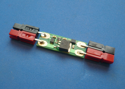
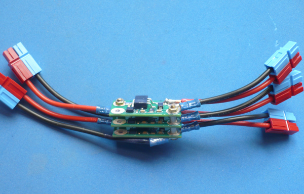
Remember this was intended to be something not much bigger than the connectors and for use without a heatsink, for battery combining, etc. 20 A is fine for a lot of purposes. Going higher can be done simply by paralleling up the boards.

IDstack136.jpg


To get above 20 A continuous in one unit can be done, but it would require not only heatsinking the FET, but beefier connections to the board, so it would be a very different type of package.

Nick
 
Gentlemen,

I was concerned enough about the current handling capability to run some further tests. I compared one of these Ideal Diode modules as shown, another one with a small heatsink glued on, with 2 Schottky diodes, one bolted to a sheet of aluminium and the other one naked.

Here's the forward voltage drop
View attachment 1

So far, so good; the ideal diodes are winning hands down.
But here's the temperature (not perfect plots, they were taken with an IR thermometer, but they are an indication)DiodeTemp1.gif

My aim was to create a diode unit that was not much bigger than the cable and connectors. But on the basis of that temperature plot, I wouldn't want to run these miniature units at more than 15 A continuous current. Therefore, I'm going to delay the idea of making a batch of these.

But the good news is that it doesn't take much heatsinking to make them better than a Schottky. Up to 20 A one of these ideal diodes on a small heatsink runs cooler than a TO-220 Schottky diode on a big heatsink, and it wouldn't take much design work to take that to higher current.

Nick
 
Tiberius said:
I wouldn't want to run these miniature units at more than 15 A continuous current. Therefore, I'm going to delay the idea of making a batch of these.
But... did I understand they *can* be stacked for more current handling?
 
TylerDurden said:
Tiberius said:
I wouldn't want to run these miniature units at more than 15 A continuous current. Therefore, I'm going to delay the idea of making a batch of these.
But... did I understand they *can* be stacked for more current handling?

Oh yes, that's true. And it may even be a better option than putting multiple FETs on one board.

Nick
 
Hi came from the future.

Where can I buy such a device that can handle atleast 10A continues 52V?
I'd like to use it to isolate the charging port for the battery when a charger is not connected and over all prevent reverse oltage if an incompatible charger gets connected.

Thanks.
 
Back
Top