your8up2
1 µW
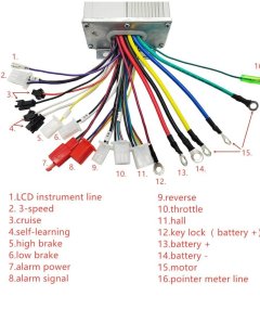
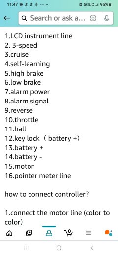
I need to figure out what the abbreviations on this pcb stand for to try and re-wire this thing after someone cut all the end connectors off. Any help would be greatly appreciated and applied to my project. Thank you in advance


You can't. The controller doesn't support a display, and the SW900 only works for specific controller brands, and yours isn't one of them.I've been studying these control boards relentlessly.Night and day asking the internet and every kind of way for refrazing my sentences and trying words from different countries. I still cannot match up the SW900 display with this Motoberry 40 to 80v controller it does say it has a 41v lvc.
(low votage cut).so I only have a 36v battery that charges up to 40.9 volts. No matter what I do I can't not get more than 3.6v Everywhere I check. Lvc could be the problem or not having the same plug as my last controller. I though I could still supply power enough to test more than I'm able to. My question is, is how would you hook up the not SW 900 display plug to a controller that does not have the same plug coming out of it? I think I had it right. But I could not find a place.
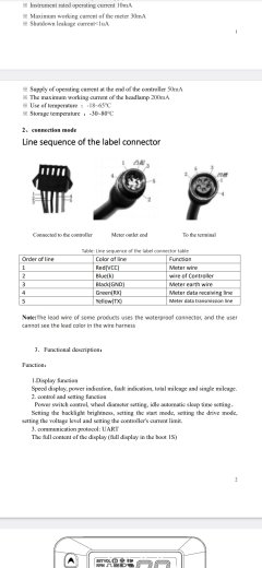
For the yellow transmission line, I figured I'd power it up.See a few things and then try to figure it out.But I got 0 power on the display
Except for the 3.6v at some areas. So I got power from the alarm plug.I connected the green SW 900 to the green line on #16 green and then the blue line to num 1 .But yellow's not hooked up and I don't know what or where a "TX" like my other controller had. Nevertheless , I don't get any power to display help , please
I can use this without the display.In other words , if it would have to have that same plugYou can't. The controller doesn't support a display, and the SW900 only works for specific controller brands, and yours isn't one of them.
UART... PROTOCOL??You can't. The controller doesn't support a display, and the SW900 only works for specific controller brands, and yours isn't one of them.