Inductance What is it what does it do? Collosus has 8uH!

rhitee05 said:
Just to point out, inductance by itself doesn't matter. It's the L/R ratio that matters. Two motors could have the same inductance but different resistances, and one of them will be easy to use and the other will smoke the controller instantly.
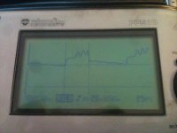
The chart big moose pionted out shows how resistance has little effect on phase amps.
I do agree some resistance will help but from what i see playing with big-mooses spread sheet you want to lower the resistance as low as possible and get the inductance up to a level the controller can handle. Because an inductor works kind of like a resistor as it charges if it takes the right amount of time to charge then it will not alow to much current to flow and blow your controller
The benifit of using inductance to limit current rather then resistance is increased efficiency!
 
In fact i know someone who has a motor harder to run the collossus and he rewound it with more resistance then collossus and it still made controllers freek out!
 
The rate at which the current rises or falls is governed by the system time constant, which is L/R. If you have a smaller R, then the time constant is larger (good) and losses smaller (good). A larger R will reduce the time constant (bad) as well as increase losses (bad). Obviously a smaller R is desirable for both reasons.

I'm just pointing out that it's silly to make a blanket statement like a motor must have XXX inductance to be controllable. The absolute value of neither L nor R matters by itself, only the ratio of the two matters (for what you want to do here).
 
Arlo1 said:
In fact i know someone who has a motor harder to run the collossus and he rewound it with more resistance then collossus and it still made controllers freek out!

That's because it was exactly the wrong thing to do!
 
rhitee05 said:
The rate at which the current rises or falls is governed by the system time constant, which is L/R. If you have a smaller R, then the time constant is larger (good) and losses smaller (good). A larger R will reduce the time constant (bad) as well as increase losses (bad). Obviously a smaller R is desirable for both reasons.

I'm just pointing out that it's silly to make a blanket statement like a motor must have XXX inductance to be controllable. The absolute value of neither L nor R matters by itself, only the ratio of the two matters (for what you want to do here).
I agree but when using the spread sheet big moose provided the resistance has such a small effect on the phase amps its almost not worth mentioning. Although i will... But in my case i will find the needed inductance and make the resistance as low as possible!
 
If you are figuring the steady-state average current, the phase resistance matters (and inductance does not).
If you are figuring the current rate of rise, the L/R ratio matters.
Phase inductance, by itself, is not important in determining the current.
This is easy to show by deriving the equations from scratch.
 
Blew another controller and this time it took out my power supply. FACK this is bull shit. I am never trying to build something with any amount of decent power with a cheep controller again!. I was just trying to turn on the bike to test things in the air and 2 hall wires must have been wrong because it popped the fets in 2 stages without even turning the wheel. I am done with these controllers no more money is spent on them I will try to fix it and try to test the inductors soon. But for now Its all I can do not to smash every piece of electronics I own and go live in the bush!
 
But for now Its all I can do not to smash every piece of electronics I own and go live in the bush!

Been there, done that......my favorite is when your testing on the bench & every thing is working perfectly....take a break for some lunch & come back to the bench to find it won't work again....no surge, no stress...just wont fire up at all...I have 2- controllers that did just quit for no apparent reason.
still have 5v to the halls & 12v on the buss...but nothing works (blown main chip mayby?)

Any way, the controllers work with a better motor design...I just recieved my stock to make new flux rings for my 80mm outrunners. Going to 8 pole prs & true ABC winding & looseing the inductance killing counter winds may loose a bit of max power & rpm potentials but ...it should be easyer on the controllers. I am going for total reliability.

Keep the Faith Arlo1, your doing good work.
 
i think we all feel your pain arlo, and yep me and splinteroz could only conclude that having kfc was the cause
for an identical "dead after lunch" type blow up :x

but, it is doable, we have had the collosus sitting on a test bed putting taking 300+ phase amps continuous, over 35nm output till the windings got to 150deg c
repeatedly, without any controller issues over the last few weeks from a $750 kelly (and yes i know they are not awesome inside) -but the halls/timing may be your issue?
 
Thanks toolman and thud. Yes I am sure the hall wires were wrong. I had a local electric guru come and help me scope the hall out-puts and match them to the corresponding phase wires. We found three that match and I labeled them. But its not A,B,C, is A-B, C-A, B-C so I have to read where those go in the controller. Im just used of hooking up something and giving it light throttle and if it twitches but doesn't turn then you just switch hall wires till it does.

The sad thing is I hooked up the inductors and there was nothing and I had it fed off 20s lipo I brought the voltage down to 82v so the controller had a better chance. But.... when having problems with my giant Anderson's I unhooked the battery and hooked up my 100v charger and got the power in going then found problems with the connectors on the inductors and by passed them thinking maybe they were doing something funny to make it not run then one slight twist of the throttle and now my bmx charger is toast and my controller has two phases with some shorted fets :?

The other shitty thing is this Saturday is my house warming and I have promised lots of people they have to try my bmx....
I really tried so hard this time to be as careful and patient as possible and just got let down due to a cheep china controller that doesn't monitor phase current~! I do intend on a better controller but i really don't know what to get.
 
Thud said:
Any way, the controllers work with a better motor design...I just recieved my stock to make new flux rings for my 80mm outrunners. Going to 8 pole prs & true ABC winding & looseing the inductance killing counter winds may loose a bit of max power & rpm potentials but ...it should be easyer on the controllers. I am going for total reliability.

Keep the Faith Arlo1, your doing good work.
I have some stock as well I just purchased a honda dio scooter I made a flux ring and found a stator for my gf's bws scooter and I will be making them both hybrids! :mrgreen:

But as for the inductance killing winding.... When I get one or both my L/C meters I will mesure collossus with a few different wind patterns and post pics/video and results so we can realy see what the center post does to it! Then I will proceed to design or redesign a motor to work better and need less if any external inductance!
 
When the motor starts out from a standstill, it's going to look pretty much like a dead short to the controller and the FETs might blow instantly when you apply throttle if the peak currents go over their limit. With a good (fast) current limiting circuit, the controller can shut off the drive before it blows even with a near-short on the output. Cheap controllers can't do this. Even expensive ones have a hard time with this.

Adding coils in series will make it take a little longer for the current to build up to the destruction point. The added resistance of the coils may actually save the controller more than the inductance.

A more advanced controller might help, but it could still blow up without enough inductance/resistance.
If you test at a lower voltage first, your chances of blowing the controller will be much less.

I would suggest winding coils around some PVC pipe in a single layer using wire with very thin insulation to maximize the inductance for a given size. Multiple strands of magnet wire in parallel might work OK, but hard to do in a single layer.
If you use multiple layers, you can run into heat dissipation issues and possibly melt the insulation. With magnet wire, this is not so much of a problem as the wire can transfer heat from one layer to the next reasonably well. With regular hookup wire, the layer on the bottom will have it's heat trapped in and get hot. With no core, you need a really big coil, probably about the size of a soda can at least.

The proximity of the coils to each other and to the frame will have an effect too. There might be a way to arrange them so they assist each other (mutual coupling).
 
Sorry to hear about your controller and charger.

One thing you could try if you still would like to measure the inductance of the motor with your scope is putting some resistors in series with each phase to limit the current. The problem with this is you'd either need to apply a very small voltage or use really high power resistors. You could get away with lower-rated resistors if you used a higher value, but I think that would make the transient too fast for your 'scope. For example, you could use 1k resistors and the power would only be a few watts, but the transient would be 10,000x faster - I'm guessing your scope is only good for a few MHz at most (that would be 50-100 MHz).

Fechter's suggestion about the inductors is a good one. You'll get more inductance per length of wire if you use a smaller diameter pipe as the form, and I would stick to a single layer or at most two. I also think you should go directly to using a larger wire or parallel strands for lower resistance. I'm fairly certain that mutual coupling is to be avoided, as it would tend to cancel out some of the inductance.

I tried running a few numbers based on some of the estimates you put up earlier. At one point you mentioned 8 us rise time for the motor by itself. Even though that's probably too long, if we assume that's the time constant and take 9.3 milliohms as the resistance, you get an inductance of only 75 nH. Considering that the actual inductance is probably lower, that's very very small! So small in fact, that we might as well assume the motor has zero inductance when adding external inductors.

To figure out how much inductance we need, the first thing to consider is how long the time constant must be, relative to the PWM period. I believe you said 62 us earlier, from which I'll assume your controller runs at 16 kHz. Running 82 V @ 9.3 milliohm nominal resistance, the un-limited phase current would climb to about 8800 A. Normally I would say that a time constant of 4x or 5x the PWM period is probably adequate. But if you look at the worst-case, that could allow a peak current of almost 1600 A! Bad news. We have to make it wayyyy longer. At 20x the peak current could be 430 A. That seems like its probably doable, considering that you shouldn't see that in real life unless you go to 100% throttle at standstill.

Ok, so we need a time constant L/R of 20x the PWM period. For 16 kHz PWM, that works out to 1.25 ms. If you could make a perfect, superconducting inductor, then about 12 uH would be enough. Not gonna happen unless you put a LN2 tank on your bike. :) Keep in mind that to achieve this, the extra inductors need to have a L/R ratio higher than 1.25 ms - so they'll need to be big and use heavy-gauge wire. I pulled up that calculator to try to come up with an example. Winding on a 1" dia pipe, two layers of 8 AWG over a 3" length gives you 43 turns and an inductance of 15 uH. That works out to about 12.6 ft and 7.9 mohms of resistance. If we combine two of those in series with the motor, we get a total L/R ratio of 1.2 ms which is pretty close to where we'd want to be. There are a lot of ways you could make a suitable inductor, so this is just an example of what is probably required. In place of the 8 AWG, you should be able to use 4x 14 AWG and get approximately the same results. Magnet wire is definitely better for this than regular insulated wire, though. Besides heat issues, the calculated inductance won't be valid for the thicker insulation. Those are pretty serious inductors, but not totally outrageous.
 
Ritee.
I am realy trying to uderstand the L/R ratio thing I found a section online explaining a car at a speed takes longer to stop with lower resistance... But I am trying to wrap my head around that with electricity.

As for the diameter of PCB I used 1.875" od pipe all I am looking for at this point is a safe zone for collossus to run.

I play with the chart from big moose and see resistance matters but the inductance is what realy matters. So I will have to lern what is off. But for now I am just using a single strand of 14 awg magnet wire for winding them to find the numbers that work then go from there. Once I find a safe number I will figure out what works with thicker wire. I have a roll of 10awg and 2 rolls of 12 awg magnet wire on their way as well. I have already realized magnet wire will be best and once I have inductance meters I will try parrallel strands to see how that effects it all!
 
rhitee05 said:
I'm guessing your scope is only good for a few MHz at most (that would be 50-100 MHz).
•up to 2MHz analogue bandwidth
 
The more I lern about this the more I realize the guys trying to run small RC controllers on the big out runners should be more worried about inductance then adding caps. The Caps absorb the sudden pulses where as the inductors try to resist them!
 
Arlo, they need both. The shut off dI/dt event creates spikes that kill the FETs. There is "another" method that can help abate the spikes called snubbers. It is a grey, almost black art to design them, and you need some voltage headroom on the FET for a snubber to operate.

You are doing good work, and earning your masters degree in controller. The learning curve is difficult and expensive. Keep in mind the pro's have teams of PhD's modeling and designing the multi kilowatt controllers that are in vehicles. It does not come cheaply. There may be just a "few" parts compared to a TV or satellite receiver, but the art is in how they are laid out, and how the bypassing, snubbing, timing and low inductance buss bars are fabricated.

BTW "the equation" of state is on the top of my spreadsheet in one of the cells.
 
bigmoose said:
Arlo, they need both. The shut off dI/dt event creates spikes that kill the FETs. There is "another" method that can help abate the spikes called snubbers. It is a grey, almost black art to design them, and you need some voltage headroom on the FET for a snubber to operate.

You are doing good work, and earning your masters degree in controller. The learning curve is difficult and expensive. Keep in mind the pro's have teams of PhD's modeling and designing the multi kilowatt controllers that are in vehicles. It does not come cheaply. There may be just a "few" parts compared to a TV or satellite receiver, but the art is in how they are laid out, and how the bypassing, snubbing, timing and low inductance buss bars are fabricated.

BTW "the equation" of state is on the top of my spreadsheet in one of the cells.
Thanks big moose. That meens a lot coming from you. I ultimatly never give up even though I now have a kink in my neck lol.
I knew this was going to be a challange so I will get it. As for the snubbers ... Makes me wonder if with a motor like collossus thats also part of the problem. Inductance will help but I will never run a controller at the max rated voltage with collossus again! I am already thinking about a 32s battery system with a 5 turn instead of 4 turn like the oem collossus is to help increase the inductance internaly and get the rpm back up with more voltage! But one thing at a time. So If I can get out of work just early enough to test collossus before shoping with the gf for our house warming tomorow (some red wine will help im sure ;) ) and I will just see if under free wheel load (no load) what the inductance looks like on the scope with ~50uH per phase lead. I have a feeling I need more!
 
Arlo, at the day job we "sneak up on the operating point." Like Rhitee said, limit your voltage, and use a current limited power supply if you can in stead of batteries. I have 3 lab supplies rated at 50 volts and 50 amps each in my personal lab. They max out the sub panel, as they are old school iron anchors and not switchers like our more modern colleague, Luke, but it keeps you from peaking a kilo amp through a piece of silicon.

Also, wait until you get your little inductance meters so you can measure the inductance of your coils. Run a piece of soft steel rod down the middle of the coils if they are too low. Without laminations you will heat the heck out of the steel rod, but you don't care about hysterisis losses at this time. Target for 100 to 150 uH to start with. You can work your way down by partially removing the steel rod.

A step at a time, shaken not stirred. We call it "iterative refinement." It works in the big lab, it will work in your lab. Luke of course, uses the DARPA model, All in all the time, it works or it's a cinder. If it burns to the ground, sweep the hangar clean and start with another contractor! :lol:

PS: for a perfect inductor (no R) V = L dI/dt or V/L = dI/dt what you are trying to do is slow down the rate of rise of current the dI/dt term so that the controller has a chance to shut off I before it "builds" to catastrophic levels. You do this by reducing V the driving voltage, or adding L . Easy, right? :twisted:
 
bigmoose said:
Arlo, at the day job we "sneak up on the operating point." Like Rhitee said, limit your voltage, and use a current limited power supply if you can in stead of batteries. I have 3 lab supplies rated at 50 volts and 50 amps each in my personal lab. They max out the sub panel, as they are old school iron anchors and not switchers like our more modern colleague, Luke, but it keeps you from peaking a kilo amp through a piece of silicon.

Also, wait until you get your little inductance meters so you can measure the inductance of your coils. Run a piece of soft steel rod down the middle of the coils if they are too low. Without laminations you will heat the heck out of the steel rod, but you don't care about hysterisis losses at this time. Target for 100 to 150 uH to start with. You can work your way down by partially removing the steel rod.

A step at a time, shaken not stirred. We call it "iterative refinement." It works in the big lab, it will work in your lab. Luke of course, uses the DARPA model, All in all the time, it works or it's a cinder. If it burns to the ground, sweep the hangar clean and start with another contractor! :lol:

PS: for a perfect inductor (no R) V = L dI/dt or V/L = dI/dt what you are trying to do is slow down the rate of rise of current the dI/dt term so that the controller has a chance to shut off I before it "builds" to catastrophic levels. You do this by reducing V the driving voltage, or adding L . Easy, right? :twisted:
Yup its all coming together and I got good news. Its running and never sounded so good with no resets! Video to come.
 
OK so I think I need 2 times the inductance and this is kinda close to the test on the X5 (which I feel only lets my controller live because of the 20x more resistance!) [youtube]oQYTp66tT_Y[/youtube] In this video I test using a shunt that is made from a length of 8 awg wire with multi meter probes crimped in each end. The length is a perfact number to make it read amps in the milivolt scale!
 
Small load test. I will do more test soon. And this is with the phase current set at 90 amps and the rated current set at 34 amps![youtube]yWqNpffJmZk[/youtube]
 
Here is some scope pics it looks to me like the build time is 12uS before the big spikes the total on time was 25uS if anyone has an imput as to what I am seing and if I am wrong about the build time being 12uS pleas let me know. IM in new teratory!
 

Attachments

  • 008.jpg
    008.jpg
    48.6 KB · Views: 1,976
  • 009.jpg
    009.jpg
    47.1 KB · Views: 1,974
  • 007.jpg
    007.jpg
    49.6 KB · Views: 1,973
  • 006.jpg
    006.jpg
    50.4 KB · Views: 1,975
  • 005.jpg
    005.jpg
    47.1 KB · Views: 1,975
  • 004.jpg
    004.jpg
    47.3 KB · Views: 1,975
  • 003.jpg
    003.jpg
    47.3 KB · Views: 1,975
  • 002.jpg
    002.jpg
    49 KB · Views: 1,974
To back out the inductance from the scope pictures, you need to know the BEMF provided by the motor at whatever speed it was running as well as the battery voltage. That's somewhat inconvenient at any speed other than zero.

- Can you run the test with a locked rotor?
- Please report the battery voltage being used for the test. To be easier on the controller for the test, use the barest minimum battery voltage that your controller will permit. If it will run on 12V, then feel free to use 12V. This will reduce both the ramp rate, and the peak current, since both are proportional to the input voltage. It will be harder on the controller^D^D^D^D^D^D edit: measurement, but much safer.
- The current signal is barely showing up on the scope. And it will be even harder with the lower voltage supply. Maybe increase the gain by 10x by lengthening the wire? A higher shunt resistance will affect the measurement at higher DC current levels, but it shouldn't be too bad below 50m or so... maybe.
- Where is the shunt connected, exactly?

V = L*dI/dt

When resistance is neglected for a short span at low current,
L = V*delta_t / delta_I

over the rising half of the signal.
 
jdb said:
To back out the inductance from the scope pictures, you need to know the BEMF provided by the motor at whatever speed it was running as well as the battery voltage. That's somewhat inconvenient at any speed other than zero.

- Can you run the test with a locked rotor?
- Please report the battery voltage being used for the test. To be easier on the controller for the test, use the barest minimum battery voltage that your controller will permit. If it will run on 12V, then feel free to use 12V. This will reduce both the ramp rate, and the peak current, since both are proportional to the input voltage. It will be harder on the controller, but much safer.
- The current signal is barely showing up on the scope. And it will be even harder with the lower voltage supply. Maybe increase the gain by 10x by lengthening the wire? A higher shunt resistance will affect the measurement at higher DC current levels, but it shouldn't be too bad below 50m or so... maybe.
- Where is the shunt connected, exactly?

V = L*dI/dt

When resistance is neglected for a short span at low current,
L = V*delta_t / delta_I

over the rising half of the signal.

That was a start voltage of 82 with 20s lipo it may have sagged a bit but not to much because it is a 10 ah 20-30c and basically new pack.
I used that shunt because I built it to hook to a multi meter and when you use it you put the multi meter on the millivolt scale it reads millivolts but it just works out the every millivolt drop across the shunt it 1 amp current! I also want to compare it to the voltage drop across a inductor I will be running more test on Monday.
 
Back
Top