Arlo1 said:jdb said:To back out the inductance from the scope pictures, you need to know the BEMF provided by the motor at whatever speed it was running as well as the battery voltage. That's somewhat inconvenient at any speed other than zero.
- Can you run the test with a locked rotor?
- Please report the battery voltage being used for the test. To be easier on the controller for the test, use the barest minimum battery voltage that your controller will permit. If it will run on 12V, then feel free to use 12V. This will reduce both the ramp rate, and the peak current, since both are proportional to the input voltage. It will be harder on the controller, but much safer.
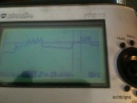
- The current signal is barely showing up on the scope. And it will be even harder with the lower voltage supply. Maybe increase the gain by 10x by lengthening the wire? A higher shunt resistance will affect the measurement at higher DC current levels, but it shouldn't be too bad below 50m or so... maybe.
- Where is the shunt connected, exactly?
V = L*dI/dt
When resistance is neglected for a short span at low current,
L = V*delta_t / delta_I
over the rising half of the signal.
That was a start voltage of 82 with 20s lipo it may have sagged a bit but not to much because it is a 10 ah 20-30c and basically new pack.
Its not the effect of the battery sag, which should be pretty much negligible at no-load. Its due to the BEMF. The V in that equation is V_battery - V_bemf - V_resistance, expanding to V_battery - Kv*rpm - I_phase*R_phase. A no-load, but nonzero-speed, Kv*rpm will be large enough that you can't say with much reliability what the voltage across the motor's inductance is.
") And to do this with a single pulse means a good trigger setup on the 'scope, too.
And to do this with a single pulse means a good trigger setup on the 'scope, too.