Inductance What is it what does it do? Collosus has 8uH!

Coming in a bit late on this one, at the risk of raising an old dead issue, but the talk about wasted energy from an inductor "after" the winding, that was going on a good many posts ago ...

Yes there's the issue of conventional current vs actual current or whatever, but could it be thought of like this:?

It doesnt matter where in the circuit the energy store goes, because it will either "push current into" the load, or "pull current out of" the load. If there's a closed circuit that goes through load and energy store, then it's meaningless to say whether it's before or after.

An analogy? You touch one contact of a lightbulb directly to the negative contact of a battery, and connect the other contacts via a wire. Bulb lights up. Is the bulb before or after the battery? OK, so reverse it, touch the bulb directly to the positive battery contact, and connect the others with the wire. Is it before or after the battery now? It'll light up both ways round, even if one of them seems to be before and the other after.

But I don't claim to understand how it works, so before anyone uses this guess to radically change the way they think about the world, maybe ask your mum, or someone else you trust.

Eric
 
Erogo said:
Coming in a bit late on this one, at the risk of raising an old dead issue, but the talk about wasted energy from an inductor "after" the winding, that was going on a good many posts ago ...

Yes there's the issue of conventional current vs actual current or whatever, but could it be thought of like this:?

It doesnt matter where in the circuit the energy store goes, because it will either "push current into" the load, or "pull current out of" the load. If there's a closed circuit that goes through load and energy store, then it's meaningless to say whether it's before or after.

An analogy? You touch one contact of a lightbulb directly to the negative contact of a battery, and connect the other contacts via a wire. Bulb lights up. Is the bulb before or after the battery? OK, so reverse it, touch the bulb directly to the positive battery contact, and connect the others with the wire. Is it before or after the battery now? It'll light up both ways round, even if one of them seems to be before and the other after.

But I don't claim to understand how it works, so before anyone uses this guess to radically change the way they think about the world, maybe ask your mum, or someone else you trust.

Eric
That's quite the comment. But if you read all the posts you would see it is answered by the power flowing back into the free wheeling diodes of the mosfets.
The thing is it not like a light bulb its more like a battery or capacitor in series with the system. So when the FETs shut off and the magnetism is still decreasing in the inductors they continue to flow electrons and in DC current electrons only flow one direction.
 
This is with the full 27uH inductors In series with each phase. [youtube]DCjdBSpaqHY[/youtube]
 
And this is with two turns removed. It started as an 18 turn iron air core inductor and is now at 14 turns which I will have to acuratly test later. I am at a point I need to turn down the phase amps because of how hard it is starting to hit off the line. [youtube]VangN0vRVU0[/youtube]
 
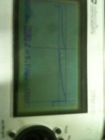
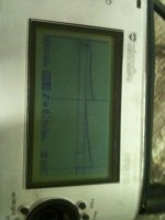
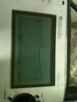
Here is some scope pictures of the shunt during a load test on the dyno as the engine accelerates.
 

Attachments

  • 032.jpg
    032.jpg
    45.3 KB · Views: 2,138
  • 031.jpg
    031.jpg
    46.2 KB · Views: 2,124
  • 030.jpg
    030.jpg
    45.8 KB · Views: 2,138
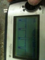
And here is some scope shots of a 1/2 throttle steady rpm with no load other then the wheel spining in the air.
 

Attachments

  • 047.jpg
    047.jpg
    48.7 KB · Views: 2,129
  • 037.jpg
    037.jpg
    42.3 KB · Views: 2,129
I hope you didnt think I meant the inductor was represented by the lightbulb in my analogy? I mean that the inductor was like the battery (stores of charge), the motor like the lightbulb (both are loads). Yes, diodes or no diodes, yes current's flowing in one direction only, but if there's a loop (and I'd guess there has to be for current to flow at all?), then does it really matter where in the loop the load is relative to the charge store? The charge store could push or pull charge through the load, depending on where (you perceived) it was placed relative to that load.

Does the presence of controller circuitry complicate it beyond that or something?

E
 
After a few more dyno runs im up to 5.96 hp. What do you guys think a 24 fet should peak out at? I made 6.5 hp with my bmx with a 24 fet and it had lots left to go just made the motor hotter. IM down to 3 turns on the inductors that were origanaly 18 turn 27uH inductors. It was neat to see the power and top speed come up as I pulled loops off them. DO you guys think I should do this luke style and keep pulling turns off till there is none? The other thing is the wire from the inductor is all still there so the is some resistance/inductance from it left over as well. I think tomorow I will try removing the inductors and just try it with out. [youtube]Ui0CVEbf5fg[/youtube]
 
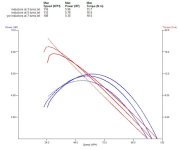
Here is a dyno graph with comparison of 3,5,and 7 turns on the inductors.
 

Attachments

  • 3,5,7 turn inductors (800 x 670).jpg
    3,5,7 turn inductors (800 x 670).jpg
    37 KB · Views: 2,076
Wow I just knoticed the reduction in torque as the inductance lowered.... Weird Now I got some thinking to do!
 
That is interesting. It looks like reducing the inductance has an effect almost like field weakening. You could have a tap on the inductor to use maximum inductance (max torque) at low speeds, then switch out some turns once the rpm builds up to a high speed. That may not be real practical considering how much current the switch would need to handle.

Alternately, you could have a mechanical mechanism to pull the core out of the coil at high speed to reduce the inductance.

The controller tends to blow up at low speeds. This is where you need more inductance.

The overall gearing (or wheel diameter for a hub motor) will give a similar trade-off.
 
Here is the rule of diminishing returns in action... You are up to about 6 hp and the controller has held together on the dyno.

Choices:
1) Remove all inductance and potentially fry controller on dyno to get to say 7 hp.
2) Leave small inductance in place, ride bike in real conditions with 6 hp, have some fun, and see if there is cumulative damage occurring or if the controller can handle 20 or 100 hours at this operating point. Take more data, figure out margins on the controller/motor combination.
 
Arlo1 said:
Wow I just knoticed the reduction in torque as the inductance lowered.... Weird Now I got some thinking to do!

Lower inductance == less current lag == timing becomes more advanced

Burtie
 
Burtie said:
Arlo1 said:
Wow I just knoticed the reduction in torque as the inductance lowered.... Weird Now I got some thinking to do!

Lower inductance == less current lag == timing becomes more advanced

Burtie
Yeh thats what I figured. If only your timing controller worked from 0 rpm up....
 
bigmoose said:
Here is the rule of diminishing returns in action... You are up to about 6 hp and the controller has held together on the dyno.

Choices:
1) Remove all inductance and potentially fry controller on dyno to get to say 7 hp.
2) Leave small inductance in place, ride bike in real conditions with 6 hp, have some fun, and see if there is cumulative damage occurring or if the controller can handle 20 or 100 hours at this operating point. Take more data, figure out margins on the controller/motor combination.
Thanks big Moose. The one thing this time around is I am running 20s 84 volts fully charged. And the caps and fets are all rated to 100. I do have room to increase the phase amps and battery amps in the settings so I will think about what I want to do and proceed. I feel like the controller can make ~10 hp at the rear wheel. I went into this thinking a 24 fet with 4110 mosfets is good for 10-20 so I think I will keep trying till I get 10 or my controller blow and I then learn the true limits "LUKE STYLE" lol.

So I have Burtie's timing board to try out. And I can up the power some more and I can remove ~4.5 uH more inductance. And the goal is ~ 10 hp.
It is entirely possible that at 84 volts I dont need any external inductance.
 
By the way the torque numbers are calculated based on the roller dia which is 3.5" and the wheel dia is 19" so you can multiply the torque by 5.43. for rear wheel torque. I talked to the program writer for the dyno and im trying to get him to write the software to choose engine or wheel torque but for now this is what i have!
 
bigmoose said:
Here is the rule of diminishing returns in action... You are up to about 6 hp and the controller has held together on the dyno.

Choices:
1) Remove all inductance and potentially fry controller on dyno to get to say 7 hp.
2) Leave small inductance in place, ride bike in real conditions with 6 hp, have some fun, and see if there is cumulative damage occurring or if the controller can handle 20 or 100 hours at this operating point. Take more data, figure out margins on the controller/motor combination.


good advice bigmoose,
with burties module and a heap of other things to experiment with haveing the bike going with 7hp is worth more than 10 or 20hp and fried..
why not enjoy the machine for a bit, and learn about all the other parts of its behavior/performance -as you now have a good test platform.

also when the lads here say 10-20hp from a 24 fet they usually mean "the CA said 150a+ peak amps and my battery was 100v off the charger, so it must be 20hp" -it isnt.
the collosus is capable of over 30hp actual power output for dyno ramped runs but a 24 fet is not the controller for this.
its always entertaining to read about a multy kw blow up, but then theres the weeks of frustrating waiting for a new controller..
fine work on getting it running by the way.
 
Thanks Tool man. I cant really ride the bike much. Its going to be inspected and registered as a u-built. As well all the batteries are on back order. So I think I decided I am going to wind the inductors back up to where they produced some pretty good torque then I am going to see what I can do with Burtie's timing board.
The only problem is how sensitive his board is to emf and this bike has lots I had to move the VR sensor to the rear roller so it would read clean enough for the dyno to work properly! I am OK at this point blowing another controller and if I can fix It I have 2 bare 24 fet boards and 2 36 fet boards to build up. I am happy I have made it this far but I know that I can get more and well.....

PS I have my X5 on my bmx powered by a 100.8 volt off the charger 24 fet system and I have watched the amps read over 200 and volts at 96 and it was not 19,200 watts or 25.7 hp at the wheel in fact I had to lower the power to about 150 continuous at 96 volts to get only 6.5 hp at the rear wheel that is where the windings/stator and magnets are at their limits. It doesn't matter if I put in 15,000 watts or 20,000 the rear wheel HP is the same and as a mater of fact the more I put in the less I get out because it becomes counter productive with all the heat it makes!
 
Looks like 7 turns is about the best torque!
So if I start there it will give me the best timing off the line (or close) then at 1000 rpm when burties bord comes active I will see if I can get the HP back up!
 

Attachments

  • 10,7,5 Turn inductors (800 x 600).jpg
    10,7,5 Turn inductors (800 x 600).jpg
    52 KB · Views: 2,163
[youtube]bgbnhyuP7Bk[/youtube]
 
Arlo1 said:
Thanks Tool man. I cant really ride the bike much. Its going to be inspected and registered as a u-built. As well all the batteries are on back order. So I think I decided I am going to wind the inductors back up to where they produced some pretty good torque then I am going to see what I can do with Burtie's timing board.
The only problem is how sensitive his board is to emf and this bike has lots I had to move the VR sensor to the rear roller so it would read clean enough for the dyno to work properly! I am OK at this point blowing another controller and if I can fix It I have 2 bare 24 fet boards and 2 36 fet boards to build up. I am happy I have made it this far but I know that I can get more and well.....

PS I have my X5 on my bmx powered by a 100.8 volt off the charger 24 fet system and I have watched the amps read over 200 and volts at 96 and it was not 19,200 watts or 25.7 hp at the wheel in fact I had to lower the power to about 150 continuous at 96 volts to get only 6.5 hp at the rear wheel that is where the windings/stator and magnets are at their limits. It doesn't matter if I put in 15,000 watts or 20,000 the rear wheel HP is the same and as a mater of fact the more I put in the less I get out because it becomes counter productive with all the heat it makes!

HOW ABOUT YOU FINALLY TRY WATER COOLING ?:)
 
But marko the motor is still cold!!!! :mrgreen: In fact I am now pulling 40.1 amps at 130km/h with burties timing bord set at 10 deg retard static and 23 deg/2000 rpm advance and 7 turns on the inductors! And yesterday you can see in the video at 110km/h I was pulling 62 amps!
Marko I dont need to cool the motor with a little 24 fet feeding it power I need more power!!!! I think I can brake 10hp by the wheekend but its not going to be easy!
 
bigmoose said:
Arlo, here is a revised spreadsheet for you to play with. Input cells are the light green. I added three TBD Motor columns for your inputting. Titled Motor A, Motor B and Motor C. Let me know if it doesn't meet your needs.

Thanks for the spreadsheet. Very useful.

Can I just make sure I understand it properly. The spreadsheet shows how quickly the current increases when subjected to a voltage. ie. during a PWM cycle.
So for a 63-74 200kv, with a typical RC ESC running at 8 or 16kHz PWM (125us or 62.5us), running at 6s LiPo, I only see the current building up to 85 or 44 Amps, assuming partial throttle and not block commutation. This does seem right. :?

Motor_Currents_6374-200kv_6sLiPo.png

If running at full throttle/block commutation, then the current can go crazy high, unless BEMF keeps a lid on things. This is what I expect will kill the ESC FETs.

I feel like I am not fully understanding this. I would appreciate if someone correct me if I have something wrong here.

The reason I am interested is that I am trying to understand the trade-off between motor speed & phase current so I can spec the right ESC and minimum speed for my friction drive project. As well as select the best PWM frequency.

- Adrian
 
Basically what that spreadsheet is telling you is how much the current can change in a given time period. So, with the 63-74 @ 6s the current can change by 44A in 63 us. If the throttle is wide open, then the next cycle it will increase by another 44A, then another, etc. The current will keep rising until the average current reaches steady-state with the BEMF and winding resistance, Iavg = (Vin - BEMF)/Rwind.

Think of this as telling you what the ripple current will be within the PWM period.
 
Back
Top