
Almasi
100 W
So that signal work or doesn't work with CycleAnalyst?
Does the noise is always the same...even with lower or higher battery voltage?
Does the noise is always the same...even with lower or higher battery voltage?
Almasi said:So that signal work or doesn't work with CycleAnalyst?
hiphilf said:OK... I would appear to have mis-spoken. The trusty counter I was using to count the pulses per wheel rotation is the thing with the noise problem. Dunno what happened to it all of a sudden, but it's giving me garbage with a known-good setup.
I was able to deduce what is happening by other means, though. I would seem the Infineon is sending out a pulse with EACH STEP of the commutation process. Instead of getting the expected 23 pulses per rotation, I'm seeing SIX TIMES that. I have two problems with this - firstly that the Cycle Analyst can't handle the high count (it'll be 138 for my wheel, and the CA can take 99 max). The only way to "fool it" would be to put in a number like, say, 92 (four times the desired number) and then drop the wheel circumference to fake out the speed and distance. Messy.
The other worry I have is that the signal may be as unreliable as the original (Shenzhen) controller I modified to add the speed function to in the first place. When I looked at only ONE hall sensor, a huge issue arose when the motor was stalled, juddering under load, or even sitting at "rest" at just the right place in its rotation. You wound up getting an artificial train of pulses - indicating speed - without there actually being any forward motion. That's what prompted me to put a circuit in place which guaranteed that the wheel had to move through a minimum of two commutation steps to register a pulse.
I'm not SURE that this is what the Infineon is doing - the signal appears to come from the MCU (via the programming header). I'm hoping that the firmware looks after the situation I'm describing - but, still, it's driving out way too many pulses to be useful without the fake-out. Sure would be nice to get ahold of the code in that sucker.
geoff57 said:what motor are you using?
I tried simmilar with a puma and got some realy daft results out, have a look at what doctorbass put herehttp://endless-sphere.com/forums/viewtopic.php?f=6&t=6629&p=134504#p134100 think iI willtake his advise and contact justin
Geoff
") ) with a Golden on it. I would get the same count from my Crystalyte, too - my own speedometer setup works fine with both (at 23 pulses per rotation). I've been playing with Justin's latest beta software - asking him to increase the count COULD be done. I think, as a programmer and knowing how much is happening inside the CA, that handling the bigger number might not be the ideal solution. Each pulse of the speed line generates an interrupt to the MCU, which is how it counts 'em without missing any. If all the ISR is doing is "counting", this is no biggie in terms of timing. But if it's holding the count or performing any math, this could be a big hit.). This is definitely not the hardware issue that is described in the above link, though. That's all about using a magnetic reed switch as a speed input, and is addressing contact bounce of that mechanical switch.
) with a Golden on it. I would get the same count from my Crystalyte, too - my own speedometer setup works fine with both (at 23 pulses per rotation). I've been playing with Justin's latest beta software - asking him to increase the count COULD be done. I think, as a programmer and knowing how much is happening inside the CA, that handling the bigger number might not be the ideal solution. Each pulse of the speed line generates an interrupt to the MCU, which is how it counts 'em without missing any. If all the ISR is doing is "counting", this is no biggie in terms of timing. But if it's holding the count or performing any math, this could be a big hit.). This is definitely not the hardware issue that is described in the above link, though. That's all about using a magnetic reed switch as a speed input, and is addressing contact bounce of that mechanical switch.First ... Thanks to K__4 for the "heads up" on the RECOM part. This has great potential.K__4 said:The shottky is in series at V+(in). So it looks like a protection diode in case of revers polarity.What would be the diode you would use shown in the pic?
May be a blocking series-shottky at V+(out) should de recommended as well, preventing harmful back current, when the Recom is powered down.
Georg


Knuckles said:I Propose that Endless Sphere DESIGN our controllers!
I'm IN!
hiphilf said:To do this right, one should feed the signal from the MCU into the divider, and the output of the divider (through a resistor) into the base of the transistor that's already on the circuit board. You get a nice open-collector (with pull-up) signal this way, rather than feeding a raw TTL signal to the outside world - but, again, just an experiment.
So, I hooked this in to one of the Infineons, set the CA for 69 poles per revolution, and tested it out...
Perfect. Reads the same as one of my other controllers that (correctly) reads out 23 pulses per rev. So there's the rub... Something else to ask Keywin if he has any control over.
I'm not going to do any further testing on the accuracy of the signal (false positives) - if I'm going to have to mount an additional package in the controller to get what I want, then I'm going to add one that I've tested and is bulletproof. In fact, I think I'll make a up a proper PCB for it - the ones I have in the Shenzhens are hand wired on perf board. I dunno if I lost everybody on why I don't like using just ONE hall signal as a speed indicator. Might be time for a YouTube video so I can demonstrate the issue...
geoff57 said:great results the reson why not to use a haal sensor for speed on a motor with a freewheel is when the motor stops spinning the wheel carrys on but the speed reads zero
bafang had a go at fitting a fourth hall sensor in the motor that pulsed 5 times per rotation required one extra wire out with the halls, for some reson they droped this i saw only 2 rear 26" models.
Geoff
.  . Other'n the ol' magnet and reed switch solution. I think I'd be inclined to epoxy two small magnets to the motor casing (opposite each other for balance), and mount the switch on a small boom mounted inside the fork, rather than use one of those spoke magnets - which I've lost many of back in the days of primitive bike computers.
 philf said:[
I dunno if someone who has more experience with the analog parts of the controller might have some ideas on how I might use either back EMF, or some other indicator of motion, to drive a similar circuit - for those who run sensorless.
I can't think of a solution for the freewheeling crowd
I'm thinking the only thing to do with a motor that freewheels


methods said:Ok, I have rummaged around all the Infineon controller threads but I seem to never find a link to the software.
Come on guys. . . Spill the beans!
-methods
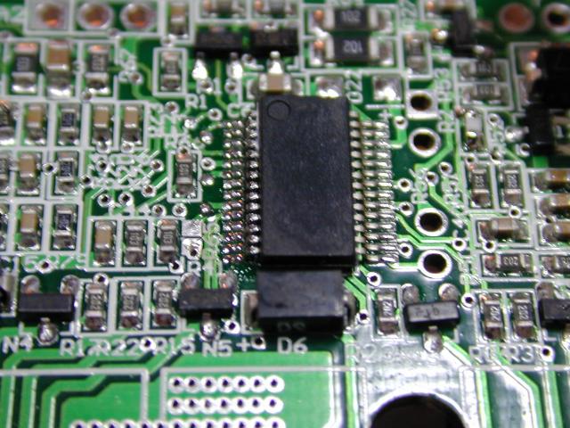
This 15-fet pcb is fascinating! It is clearly a xie-change Infineon pcb.John in CR said:Here's a 15 FET controller that comes with some motors I have. It has the XC846MCU and looks a lot like the boards you've been talking about here. Unfortunately the maker sanded the FETs, so I don't know what they are. It's supposed to be a 60V controller with 50V cutoff and 73V limit. I've been using it without issue, other than heat, in the recommended voltage range, but I'd like to be free of the restrictions and try some of the stuff you guys have unlocked.
I'd like to try some of the stuff you guys are doing, but this stuff is mostly greek to me. Specifically I'd like to figure out if there's a reverse switch, and regen braking. There's already a wire going to BK from the outside, which I'm told takes a 12V input as the signal for the electronic brake cutoff of the controller. There's the unused EBS pin, which to me would seem natural to be for electronic/regen braking. There is no DX3 pin, but others might be a reverse. How to do go about trying these things? Is it ok to carefully hook an open controller to a motor and try jumpering some of these to ground and see what happens?
Does it look like the same resistor/transistor mod would work for this controller too?
John
 .
.I agree.philf said:I'm fairly certain that ANY of the Infineon boards are built around a single programming spec.
Not gonna happen (unless John can do a software "flash" with an oxy-acetylene torch).philf said:I'd definitely be giving that programming header a whirl, though, John
