Infineon has REGEN BRAKING (and more)

Knuckles said:
The COM port connector has a smal chip and pcb inside.
It may not be possible to "hack".


To buy a "PC to Infineon" Interface cable just contact Keywin ... ecrazyman@gmail.com

Of course it's possible to hack. But if Keywin is selling them cheap enough, it may not be worth the effort. :wink: Do you know how much Keywin is selling them for?


I can't quite make out the number on the chip. Is it readable?
 
hallo Knuckles,

this chip looks like a MAX232CPE.

best regards, Georg
 
Thanks for the dongle photo,Knuckles!

Pretty much looks like a xx232 type chip with it's five 0.1uF caps for sure, so it should be a piece of cake. It wouldn't really make sense that it would be anything more complex than this for a RS-232 serial port. It's just a voltage level converter chip. I'll have to try soon on the infinion I have here - Where's the latest software to flash the controller available to download? And are there any procedures to know as to avoid doing a potentialy lethal flash to the controller?

I was planning on making my serial interface into a similar dongle to program my own controller, mostly to save board space and assembly time. However, I am hesitating to do this since I plan on having pretty much all controller paramaters configurable via computer based software. In my mind, this would make the RS-232 level converter pretty much essential to such a controller.
 
SUCCESS!

I have a few domestic obligations to fulfill, but I think you'll like the solution. The resulting product is something I've been intending to build (only sexier) for a while - those interested in connecting to their CA for data logging will be interested as well...

Cheers!
 
Fishmasterdan said:
So why cant you get regen with a geared motor?? Is there a mechanical thing inside the motor that engages the motor with the throttle is on?? If that is true why can you parrallel that.??
Most geared motors have an internal "freewheel" mechanism (although a few geared motors do not).
The freewheel allows the hub "shell" to spin (coasting) without the rotor spinning.
This freewheel is very desirable and a good thing to have (especially for just pedaling your bike).
The Bafang and the PUMA and the eZee all have internal freewheels.

Since the rotor only can apply power in the forward direction it can not "brake" the hub shell.
Likewise ... it can not go in reverse.

fechter said:
Of course it's possible to hack. But if Keywin is selling them cheap enough, it may not be worth the effort. :wink: Do you know how much Keywin is selling them for?
I can't quite make out the number on the chip. Is it readable?
Well the "fechter" (Eric Clapton is GOD) price from Keywin is ZERO $$$. For everyone else I would think under $50 delivered.
The rat bastards (http://www.xie-chang.cn) sanded off the dongle chip identification. :roll:

ZapPat said:
Pretty much looks like a xx232 type chip with it's five 0.1uF caps for sure, so it should be a piece of cake. It wouldn't really make sense that it would be anything more complex than this for a RS-232 serial port. It's just a voltage level converter chip. I'll have to try soon on the infinion I have here - Where's the latest software to flash the controller available to download? And are there any procedures to know as to avoid doing a potentialy lethal flash to the controller?
Rock'n'Rolla ... Hack that Sucka! :twisted:
Download the software (free) on my tech post here ... http://endless-sphere.com/forums/viewtopic.php?f=16&t=7361#p110931
Just make sure the controller is DISCONNECTED from the bats when flashing.
-Peace Out (and a shout out to K__4)

PS ... Right now (as far as I know) only Keywin, geoff57 and me have the PC interface.
geoff57 is VERY knowledgeable about using the interface. He is a GOOD TECH DUDE!
I would be very happy to see many many more folks using this very cool (essential) accessory. 8)
 
hi
I am away from home computer at moment i have some great hi res pics they are BIG
i have one more but i have to resize it
the markings on the chip make me think you have it right with this max 232
i hope this helps you


geoff
 

Attachments

  • pc link 1.jpg
    218.6 KB · Views: 2,713
  • pc link 2.jpg
    183.7 KB · Views: 2,683
  • pc link 4.jpg
    475 KB · Views: 13,041
  • pc link 3a.jpg
    355.5 KB · Views: 13,044
Sorry for the delay (for anyone who's actually been polling this thread :)

It took me most of my morning to get "stuck in" to this sticky problem, and that wound up running into the early afternoon - then I was on the hook to deal with "real life". Simply put, failure of the latter (getting groceries, etc.) would have meant not having much to eat for dinner...

Anyways...

I started out this morning fully intent on putting together a simple MAX232-based serial converter to enable a TTL-level conversation between the software that Knuckles was kind enough to post the link to, and the Infineon controller. I'd picked out a piece of perf board, a handful of caps (the MAX232 needs 4 of these on top of the usual decoupling requirement), and the other wire and connectors needed to get going on this.

It was while I was rummaging for a DB9 connector (when's the last time I'd done something with one of THOSE?b) that I caught myself. I was trying to build an interface between an RS232 serial port and the TTL level programming header on the controller. Meanwhile, the computer I use to talk to the microcontrollers on my bike is a laptop that doesn't even have a serial port. When needed, I've been using one of those USB to RS232 dongles that has never really given me pause to think about what was inside it - until now...

Why was I trying to down-convert RS232 using a MAX232? Why was I mumbling about the fact that - however I did this - I'd STILL have to find a 5V supply to run the controller board during the programming process?

The blinding flash of the obvious hit me at that point - instead of building yet another external device/wiring harness - I SHOULD be modifying what was right in front of me. Rather than ADD a MAX232 to what was going to be connected to my laptop through the USB serial port emulator - why not REMOVE the signal converter which this device employs, and simply pass the TTL output of the USB HID device emulator directly to the outside?

To keep the story short, this is what I elected to do. I have a couple of different styles of these USB-RS232 dongles kicking around (not because I *need* them, but because I wound up purchasing additional ones when I was unable to re-locate the first one(s) I bought... but my cluttered workspace is a whole other story).

Anyone who has gone to the local Future Shop/Best Buy/Office Place/Business Depot/Staples/Circuit City - or whatever outlet you have in your particular country - may know that the price of one of these USB to RS232 dongles is somewhat out of line. I have one unit that I *know* I paid close to $40(CDN) for, and why would I want to bastardize THAT? But I have others that I came by almost "free", and which (as of this writing) can be purchased directly from Asian sellers on eBay for less than $2. It was one of these latter that I elected to hack, but they turned out nearly identical (electrically) to the over-priced ones sold in the big stores... The difference is how they are put together...

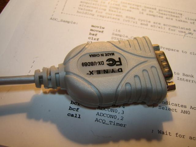
This is one labelled "Dynex" which, I believe, I got at Staples/Business Depot and for which I paid wayyyyy too much coin...

2%20-%20Dynex1.jpg


The beauty of this thing is that - with very little prodding - the innards slide out, and you can simply remove the inside covers to expose the PCB inside...

3%20-%20Dynex2.jpg


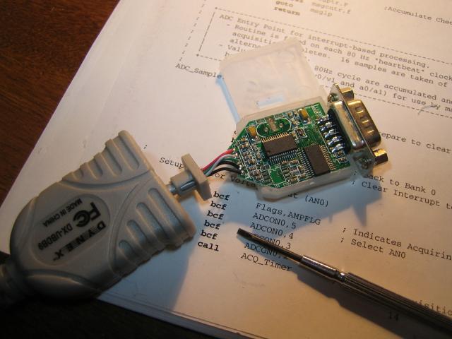
In the interest of other forum members who may want to try this, I elected NOT to use this one for this project. Instead, I used one of the "cheapie" units that (as mentioned) can be purchased on eBay for next to nothing. It's interesting to note, BTW, that the chips used in BOTH of the dongles I'm showing, here, are the same - and the driver software is the same, too. Hmmm..

The BIG difference is that the cheapies have their PCBs moulded into the connector. You literally have to slice open the sides of the thing and peel away the semi-soft shell (this isn't as ugly as it sounds)...

4%20-%20Generic1.jpg


So the object, here, once you have the board out of its shell, is to remove the chip that does the level conversion between TTL and RS232. I'm lucky enough to have an SMD rework station that would have made this easy work, but decided to do it the brute force way - an approach that anyone reading this can take - by slicing the legs off the chip I wanted "gone", and using a soldering iron to clean off the leftover legs. The thing to keep in mind is that you need a sharp tool, and you want to cut the legs into the chip body - NOT the circuit board - so that you don't cut any traces. Today, I'm sporting a huge (3/4" diameter) blister in the middle of my right palm (no, I didn't get it doing THAT :)) from chipping the ice off the driveway, so I'm using certain tools a bit awkwardly. I wound up lifting a few traces while trying to man-handle the driver chip off the board, but I wasn't really caring about this - virtually ALL of the signals that need to be jumpered pass through at least one via before reaching their target - and these are INFINITELY easier to solder to than the pads laid out for an SOIC chip.

Gadz, I'm realizing how long this post could get - so let me try to cut to the chase...

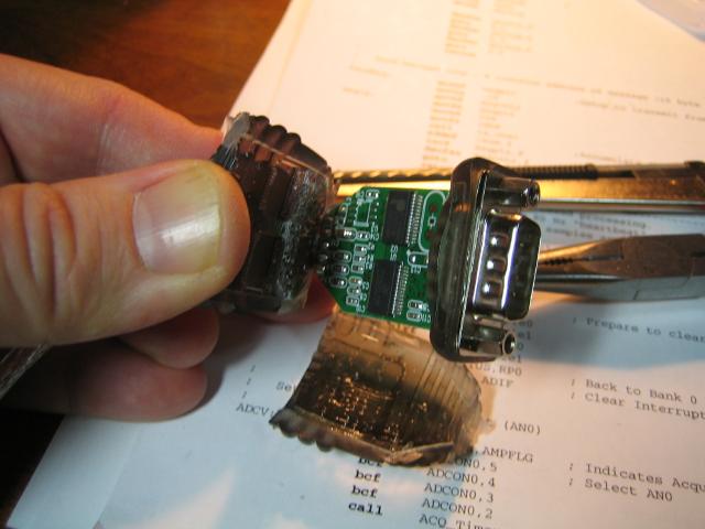
The USB controller has TTL level inputs/outputs that go to a level converter chip (to get to the +/- voltage levels required by the RS232 standard) before heading off to the DB9 connector which is the actual serial connector we know and hate. The object, here, was to remove the signal converter chip and directly connect the TTL level outputs from the USB controller to the DB9 - by simply jumping the inputs (to the now-removed conversion chip) to what used to be the output or vice-versa.

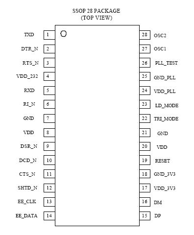
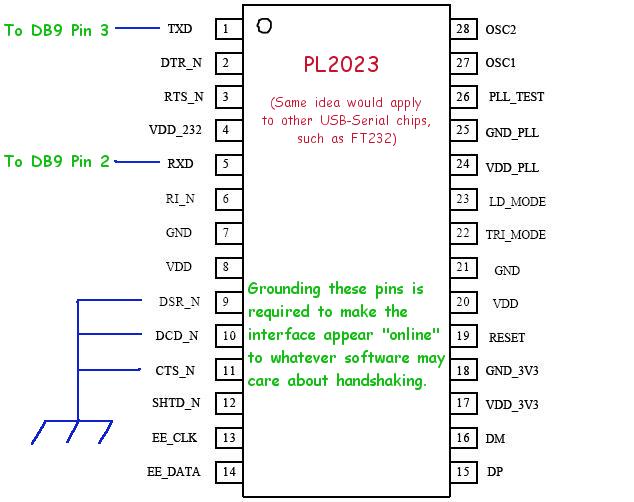
All of (three, in the end) the USB-RS232 dongles I looked at employed the same chips. Despite the popularity of the FT232, these all used the Prolific PL2303:

pl2303.jpg


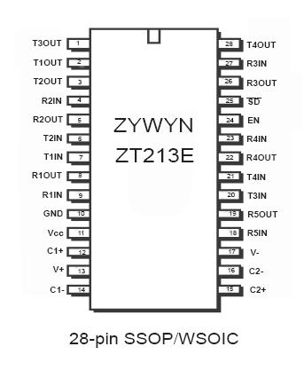
For drivers, all used the Zywyn ZT213 series driver chip:

zt213.jpg


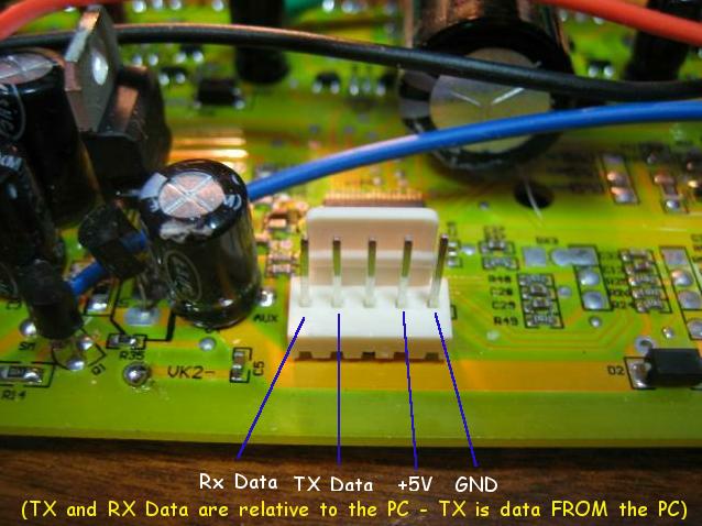
What wasn't consistent was the choice of which pins on the driver were used for what purpose. If you venture down this road, the best thing to do is to follow the pins of interest back from the DB9, and target which signals to jumper accordingly. If TX Data goes to R5OUT, then jumper it to R5IN, etc.

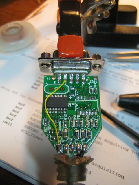
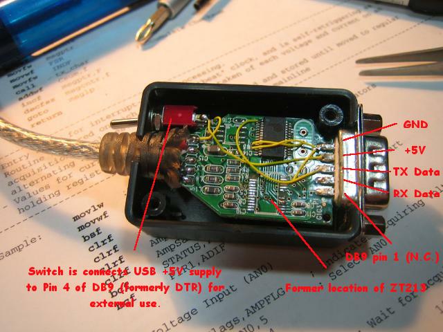
You can't actually see the jumpers in this picture (I was able to pick up adjacent vias) that handle RX and TX, but you can see that I've run a 5V power lead to (the now unused) pin 4 on the DB9.

5%20-%20removal.jpg


You can also see how many pads i ripped off with the ZT213. Didn't care - everything could be connectd to vias.

Once it was together, I looped pins 2 and 3 on the DB9 together and fired up an ancient DOS-based terminal program I have to see if the characters sent through the serial port were echoed back. THEY WERE! Woohoo!

So, now it was down to connecting this thing the Infineon. I agree wholeheartedly with what 
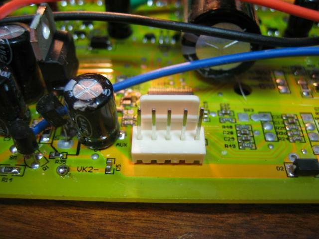
fechter posted earlier. This "touching" of tin contacts with solder pads didn't seem like a great idea to me, so I added a proper header to the controller board.

1%20-%20header.jpg


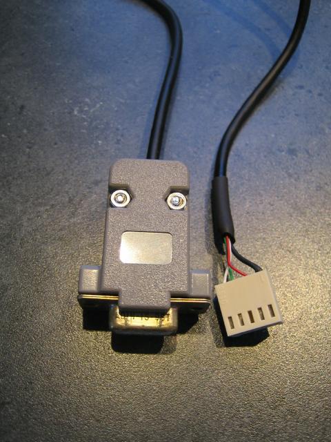
All that remained was to build a little cable to connect the (now TTL) DB9 to the newly installed header:

6%20-%20Cable.jpg


And then the acid test... If I load up the software, will it work?

...

NO.

Alright, maybe it's the subjective opinion of what "RX" and "TX" mean... Perhaps they are (as often occurs) reversed, depending on which end of the line you're standing at. Let's try reversing them...

Nothing. Hmmmm...

But, after a pause (and double checking that my earlier loop test still worked), it hit me that this program is a Visual BASIC app that uses MSCOMM32.OCX - it probably cares about handshaking! Not with the device, but in order to actually LOOK at the serial port. This thought was confirmed when I realized that my simple loop-back test didn't work in HyperTerminal (when's the last time anyone used THAT?). It showed the status of the port as being "offline". Double-"ahah".

So I added three more wires to the dongle - this time to take DCD, DSR, and CTS low (signals used to indicate "readiness" of the hardware to accept data, and that you're online). Quick test with Hyperterminal again... YES! It works properly...

Back to the Infineon...

Connect the controller, load up the program, load a sample file, hit "Transmit", and... nothing. Just waiting...

*DOH!*

Forgot to put the RX/TX wires back the way they were... Try again...

Frak. Nothing...

It was at this point that I was about to walk away for a while, and then I remembered something that Knuckles wrote on the bottom of the picture of the original cable. "Briefly Touch Flash Connector to Infineon pcb to Transmit Software Settings to the Controller". Suppose the firmware in the MCU only looks for the programming cycle during boot? I've now made this sexy cable that, the minute I connect it to the new sexy header on the controller board, it powers up the MCU and has it idling by the time I can get the software PC organized.

Different timing required...

Disconnect header from controller, load PC software, load demo file to send to controller and hit "Transmit'. THEN connect the controller.

*BINGO*

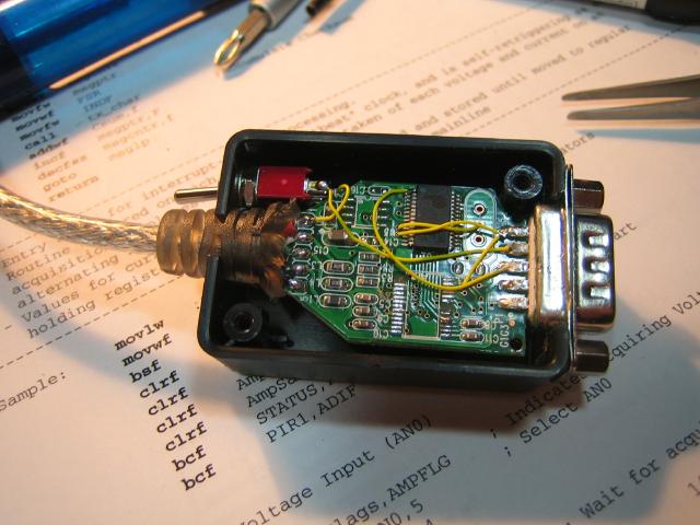
At the end of all of this, I wound up putting the modified USB dongle in a small project case, and added a switch to control the application of 5V power (through pin 4 of the DB9) separately. You can see the extra yellow wire wrap wires jumpering DCD/CTS/DSR to ground:

7%20-%20Enclosure.jpg


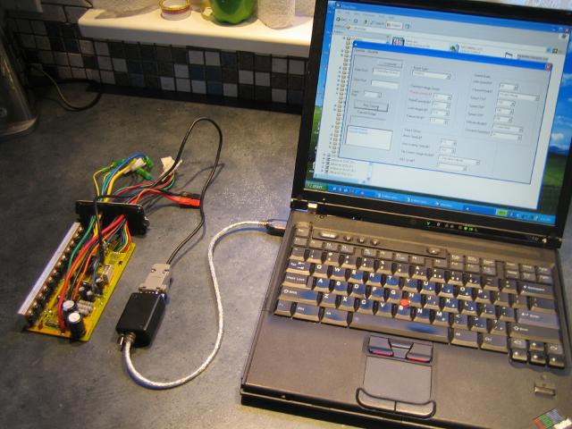
And, here, the final setup after having some fun with the settings...

8%20-%20Success.jpg


I confess, I've blown myself out of the water twice while trying to compose this (by phat phingering off the page and losing the message buffer contents) - and the subsequent efforts to re-create the story get messier with each attempt.

I'll come up with a proper schematic for all of this, but I'm hoping the gist of it comes through. I've been meaning to make a TTL-level serial interface for a while (for other purposes), but this same thing can be used to interface to other data logging devices, for example, that use TTL level serial communication.

Cheers!
Phil
 
Way to go Phil!
That's even better than a guinea pig. I'll have to come up with a new award.

Knuckles said:
The COM port connector has a smal chip and pcb inside.
It may not be possible to "hack".

To buy a "PC to Infineon" Interface cable just contact Keywin ... ecrazyman@gmail.com

OK, I'll admit that zero$ is pretty cheap, but where's the fun in that?

Phil pretty much lost me in part of the explaination, but I do have one of those USB to serial things gathering dust in the garage somewhere. It's like playing mad scientist. You either get the "It's Alive!" thrill, or you get a puff of smoke and some swear words.

Now, to trans-rate some of that code to figure out what other nifty features we might be missing out on....
 
I do ramble on a bit. You can see 1 edit, there - but upon re-reading the post, I realize it isn't as clear as my first go. Gotta stop hitting the "Back" button while I'm trying to compose. :(

I had to stop and think about the reference to "code", there... Then I realized... Yup, I like to play with microcontrollers, and isn't unusual or me to recycle an old paper program listing (I'm old-school in my need to work with hardcopy) to protect my desk when using sharp tools.

That particular listing is from a device I built which performs a subset of what the Cycle Analyst does as well as some other things that were of interest to me. Actually, it was working on that very project which brought me to the forum - and introduced me to Justin and his device at the same time. I'm going to post about that project at some point... The best thing that has come out of pursuing it, apart from that "Mad Scientist" satisaction, was that it did lead (indirectly) to Google bringing me here, and then actually meeting Justin. You don't come by people like him every day :) Nor do you come by forums as rich as this one every day.
 
hi
well done for I think my pics came too late and you took a different route hope they were good enough though.
sorry first thing I should of said when you said about putting posts on the infineon is that a switch would be needed I found this in the UK I put posts in and had the same problems as you.
I have decided that all Uk infoneons will have a connector for the PC link sold with on a 4 way JSTsm connector so the board does not need to be removed from the case, I am not sure yet for the first few I have sent down to Team Hybrid the connector comes out with all the others, these are part of TH' first shipment and having full tests with TH wheelchairs, we already know it is a great controller for ebikes, the other way to fit it is behind the plate at the other end to the rest of the cables,just unscrew the plate and plug in.
both have good and bad points what do you think?
oh and the gender of the connector is the reverse of a 4 way throttle to prevent connecting to the wrong thing.

Geoff
 
Stupendous hacking job, Philf!

I still have serial ports on all my PC's and have no USB/RS232 dongles on hand, but I will definitely try to pick up some in the future. At 2$ a hit, it might be worth using this cool hack on them so that the increasing number of RS-232 "portless" people can program their controllers too - USB is much more standard on all computers nowadays after all.

Your comments about hyperterminal becoming old stuff makes me realise that I'm slowly becoming an "old tech" generation member myself, since I was actually able to understand your whole post! "Old tech can still be usefull at times nonetheless, as we can see here in Philf's great hack work.

So this means now that I'll be able to put two controllers and two motors head to head to do some cool regen tests. This will help me to compare performance of the two different controllers and get some idea of the electrical efficiencies of these devices, one under drive and the other doing regen at the same time. The only thing is that I only have one brushless hub motor, so I might have to use my own controller with my 4kW ecycle motor for now, because I seriously doubt that the infinion-based controller can handle such a load. I'll have to look around for a used brushless hub motor though, so that I can switch the motor/controller couples around as to get some real comparisons between controllers.
 
Hey, thanks guys...

Geoff: I think the idea of putting the programming connector behind the endplate is brilliant. I was looking for small panel-mount connectors (with weather caps), but the price was ridiculous. I didn't like the idea of having a dongle hanging out of the controller that was carring unbuffered signals straight back to the MPU over "long" wires, but was going to do it anyways :) Most people's reality is that, once they've got their inaugural "play time" behind them, they'll probably leave the settings pretty much alone. Why not just run with the end plate off during this time? :)

I didn't really know how to distill what I did into a few easy to follow diagrams, so I've annotated the original pictures for clarity. Here's what the header on the Infineon board really looks like. As alluded to, the meaning of "RX" and "TX" mean the opposite, depending on which end of the cable you're looking at. I've labelled the pins, here, with "TX" meaning FROM the PC, and "RX" meaning TO the PC. Those boards that have the pin definitions silkscreened (fechter posted one) have "TX" labelled from the sense of data FROM THE CONTROLLER (RX to the PC).

Header%20Pins.jpg


The specific removal of the RS232 driver (ZT213) and where I placed the jumpers/wires probably isn't too meaningful, as no two of these dongles (from different manufacturers) are the same, even though they may employ the same parts.

The key, here, is that once you remove the RS232 driver, you've disconnected the pins on the DB9 (except pin 5 - Ground) from talking to anything. The real objective of the exercise is to go back to the USB-Serial chip and find an appropriate via or pad to allow you to reconnect the appropriate signals to the DB9. I wound up stealing what was formerly DTR (pin 4) to supply 5V to the external devices I might just hook up :)

Here's the PL2023 again - you'll find similar pins on other chips, such as the FT232.

PL2023%20Diagram.jpg


And, finally, an annoted picture of the final board - just to clarify which pins are which (the actual pin numbers on a DB9 are usually molded right in to the connector body, as to remove confusion as to which signal is which. Matters not if the connector is male or female. Pin 1 is always pin 1, though the order is reversed between the two sexes so that the number is preserved when they are mated).

USB%20Diagram.jpg


Hopefully this makes it clear enough for anyone who has a hankering to give it a whirl. Like I said, eBay is FULL of these cables (just use "usb rs232" as a search argument).

http://cgi.ebay.com/USB-to-RS232-Se...4|66:2|65:12|39:1|240:1308|301:1|293:1|294:50

The one pictured appears identical to the one I've used in this example - except the plastic was smoke grey instead of blue (they come in other colours, too).

Cheers!
 
Nice!
You win the Hacker Prize!
A (Chinese Made) Life-Size Blow-Up doll of Angelia ...
Cheers!

Hack_Prize.jpg

btw ... Here is an example asv file to play with ...
http://98.131.176.65/endless-sphere/50A_Infineon_Example.asv
(Right Click, Save Target As ...)

I use this one for flashing the 50 Amp Infineons

:roll:
 
hi
do not save with a space in the filename , the program does not like it and will not save the data.

I can't remember which but one I will check but either tx or rx is also the speed /rpm line for the CA before a signal booster.

I've got home so i will finish this post now.
if you look at the picture phil put up in his last post of the board with the pc connector pins identified on it then follow this through.
going from the pin marked tx on the underside is a track that goes to the pad /solder blob just above VK2- the track from that goes through R35 to Q1 this is the signal booster I spoke of the output of that goes to the pad on the board marked SM that a blue wire comes off this is the hall signal wire for a CA unit.
the rx line also ha another function when the controller is working but I have not worked that out yet too many components in the way!

Geoff
 
found a nice forum,
lot of engenious soldering.

may be you can use something like that:
: http://translate.google.de/translate?prev=_t&hl=de&ie=UTF-8&u=http%3A%2F%2Fwww.mikrokopter.de%2Fucwiki%2FSerCon_Anleitung%23head-f19efe4089fbaa091955b3463a8752d94a01fef6&sl=de&tl=en&history_state0=

Ist should be the SIO-Part of such an Interface.
This one is called Sercon ( Max 232 inside) an used for programming the microcontrollers in a Mikrokopter.
In the shop you can also see RS232 to TTL Konverter similar to Phil´s hack. For those who miss a V24/Rs232.
https://www.mikrocontroller.com/index.php?main_page=index&cPath=69&zenid=fc65a47985834b9d5973ae789c5e9416

here the english wiki site:
http://www.mikrokopter.de/ucwiki/en/MikroKopter/#head-1b24ee2febf167126e0e061606231563cc5b570d

best regards, Georg
 
geoff57 said:
hi
the rx line also ha another function when the controller is working but I have not worked that out yet too many components in the way!

Geoff

Woohoo! Could this be the missing status data I was searching for? It would be cool if the controller was streaming out status codes on the serial line while operating.

Gonna have to play again :) Perhaps building another adapter cable to just hook up GND and RX, to see if what's happening on that pin is actually serial data. I really gotta get me a 'scope. It would have sped up quite of few of the things I've done of late.
 
hold on
infomation is coming in I'm just not sure what information yet but i think it is to do with the shunt
geoff
 
philf said:
... I really gotta get me a 'scope. It would have sped up quite of few of the things I've done of late.
I agree, a scope would be a great and fun toy for a wakky-hakker like you! :mrgreen:

A digital storage scope is really nice to have, and some of the older higher-end ones can still be great tools for less cash on fleabay. I found myself an HP 54502A that does 400MS/s, and for my controller work it has turned out really essential. The ability to see one shot events after they happen is great! I think also that maybe the PC-based scopes are getting better too for the price...
 
just a note to say really great work philf and knuckles, I know slightly above zero on this stuff, but will certainly have a fiddle when i get some infineons.
Only thing I can add is seems alot of controllers already have 5 pin connectors for programming, pic attached of what seems common type of connector used, I would think no problem for xie cheng to add these, would make life a bit easier, keywin is sending out serial connecting cables with controllers ( wayne in south africa got a cable with some infineons from keywin)
 
Guys, I bought a 36v 350watt (25amp) from e-crazyman as a backup to my normal controller. I guess its a infineon. Board is a "EB806". It has the programming port.

Is there anything of interest that I can change with the config program?

I'm not looking to mod the heck out of it or anything... I mostly just want it as a backup. Might be good to lower the LVC a little since I'm stuck with SLA.... But thats done via hardware mods, right?

Thanks
 
The EB806 is listed as a choice in the programming software, so I'd say the answer must be "yes!".

The LVC is a programmable function - without hardware, if I understand the software setting correctly. My EB812 came with a trim pot hand soldered to the back (to adjust LVC manually the "hardware" way). Removing the trim pot and tweaking the setting through software has got me the same result.

Following what Knuckles (or was it Geoff?) posted about the convention... I'm assuming your board (based on the last 2 digits of the number) has only 6 FETs on it?

Question, bbsux - is it possible to get a good pic of the EB806 (top and bottom)? Wondering if it's a candidate for a transistor swap/add in future, and what other differences there might be between it and the 812. It would be nice to know what the 6 transistors are, too, if you can make 'em out through the conformal coating...

Cheers!
 
philf said:
The EB806 is listed as a choice in the programming software, so I'd say the answer must be "yes!".

The LVC is a programmable function - without hardware, if I understand the software setting correctly. My EB812 came with a trim pot hand soldered to the back (to adjust LVC manually the "hardware" way). Removing the trim pot and tweaking the setting through software has got me the same result.

Following what Knuckles (or was it Geoff?) posted about the convention... I'm assuming your board (based on the last 2 digits of the number) has only 6 FETs on it?

Question, bbsux - is it possible to get a good pic of the EB806 (top and bottom)? Wondering if it's a candidate for a transistor swap/add in future, and what other differences there might be between it and the 812. It would be nice to know what the 6 transistors are, too, if you can make 'em out through the conformal coating...

Cheers!

The board is definately different than the one in the pic posted, I was hoping they simply used smaller rated components...

I'll get a picture tonight when I get home.

As far as the LVC -- the software goes from 30.5 directly down to 22.5 -- The lowest I'd want to go would be 29 or 29.5... I wonder if I could make a new file and enter that voltage if it'd work...? (guess not, when I try it is blank)
 
oh and this is for my schwinn stingray electric bike BTW...

Wonder if I could do regen on it???? I don't think its geared and the free wheel is outside connected to chain for the pedals...
 
hi
You have the baby of the family that does not mean it is no good.
take a look at this translated blog I found

http://translate.google.co.uk/trans...sult&prev=/search?q=xc846&start=10&hl=en&sa=N

This should give an idea of all the controller is able to do.
Changing the LVC via the pot is becoming unnecessary the LVC programming is enough and with some pressure we might be able to get a few values added regen is limited to 48v over that hardwire modification is required at the moment this also alters LVC settings, requiring an offset in the programming of the Infineon to still get the LVC we want.
As for the transistor mod that is for use with battery packs over 48v not really in its range a good view of the area around the power resister will give us a better idea as to whether

it is possible.


Geoff
 
Back
Top