Infineon has REGEN BRAKING (and more)

bbsux said:
Is there anything of interest that I can change with the config program?
There are really only two meaningful pcb hardware mods for the Infineon IMO.
1) Alter the power resistor circuit to allow "Any Voltage" (aka Transistor Mod)
and
2) Alter the R12 MCU circuit to alter the LVC and the maximum regenerative braking voltage.

All other controller functions can be addressed in the Infineon software.

The "Transistor Mod" is a subject in and of it self and I'll leave that to another thread.
The R12 "tweak" is pretty easy to explain so I'll describe that here.
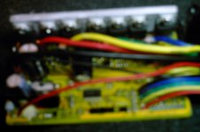
R12 Circuit
A pin out on the MCU connects to the surface mount R12 resistor and then to ground. The stock Infineon R12 value is 1200 ohm. The MCU pin out is fed a tiny amount of current from other resistors on the controller board but the value of R12 dominates the actual pin out voltage for any given battery voltage. With R12 at 1200 ohm, the MCU pin out will vary between about 1 to 6 volts depending on varying battery voltages (20V to 90V) as provided from the thin red (or thin orange) controller battery (+) “ignition” wire.

The MCU reads the R12 voltage as a way to “know” the battery voltage at any point in time. The MCU is programmed with the assumption that R12 = 1200 ohm. Altering the R12 value will “trick” the MCU. This is the basis of the original variable LVC potentiometer that was used BEFORE I got my hands on the software interface.

The controller MCU “sets” the LVC based on the R12 pin out voltage.

BUT …
The MCU (apparently) CAPS the maximum regen braking voltage based on the R12 voltage also. It appears that the Infineon was “hard” programmed with a maximum regen braking voltage of about 60 volts. The max regen voltage value is apparently fixed at 60V and cannot be changed with the software interface (it would be nice if the max regen voltage changed when the software LVC is changed ... but this does not seem to happen).

But changing the R12 value is very easy to do. Adding another resistor from the underside of the board can lower R12. R12 can also be disabled (by drilling a small hole) and replaced with an all-new resistor value or a potentiometer (also from the underside of the board). More details about the R12 circuit are found here ...
http://endless-sphere.com/forums/viewtopic.php?f=16&t=7361#p110932

Changing R12 will change BOTH the LVC AND THE MAX REGEN braking voltage.
Lowering the R12 resistor value below 1200 ohm INCREASES the "real" LVC.
(and also increases the max braking voltage above 60V)
Increasing the R12 resistor value above 1200 ohm DECREASES the "real" LVC.
(and also decreases the max braking voltage below 60V)

EXAMPLE
Install a 2880 ohm in parallel to R12. R12(new) now equals 847 ohm.
1/R12(new) = (1/1200) + (1/2880), R12(new) =847

Now if you program the LVC to say 20.1 volts, the “real” LVC becomes 28.5 Volts
(20.1v) x (1200) / (847) = 28.5v
AND
The “real” max regen voltage becomes 85 Volts
(60v) x (1200) / (847) = 85 Volts

file.php


This is exactly how I got the Infineon to regen brake my 72V NiMH battery packs.
Works real nice too! :D
 
philf said:
Question, bbsux - is it possible to get a good pic of the EB806 (top and bottom)? Wondering if it's a candidate for a transistor swap/add in future, and what other differences there might be between it and the 812. It would be nice to know what the 6 transistors are, too, if you can make 'em out through the conformal coating...

Cheers!
p50nf06

my camera really sucks heres the best ones...
 

Attachments

  • DCFC0004.JPG
    DCFC0004.JPG
    247.3 KB · Views: 9,542
:shock: Wow, lots of excellent information here guys, thanks a lot.

That translated Chinese link is amazing, and Knuckles with his resistor tricks, It just keeps getting better, you guys are great.

Fortunately I'll only be running a 48 volt Infineon controler, so my mods for regen would be a little easier.
 
Yup, kinda hard to glean anything real from the pics - but thanks, bbsux, for posting.

As you indicated - DEFINITELY a different layout. Those transistors are good for 60V, and 50A. But not at the same time :).

I'm turning into a junkie for this stuff. When I see a controller that's different, I almost want to acquire one "just to see". I've gone and ordered one of those "BAC 281" controllers from the Golden Motor site because the thing was too interesting to resist. The cover will be off that puppy before I even try it out, I'm sure. Will post pics...
 
Hey philf,

I'm not really up on TTL but do you think this product would work (out of the box) for USB to Infineon?
http://www.ftdichip.com/Products/EvaluationKits/TTL-232R.htm

Found this for $20. Looks nice and compact.
http://www.makershed.com/ProductDetails.asp?ProductCode=TTL232R
Direct USB to TTL with 5V power.

"The new TTL-232R is a USB - TTL serial converter cable which will allow for a simple way to connect serial TTL level devices to USB.
The TTL-232R uses a FT232RQ chip which is housed within the USB "A" connector. A 1.8 meter (6 foot) cable is terminated with a 6 way 0.1" pitch header socket which provides access to the Transmit (Tx), Receive (Rx), RTS#, and CTS#, as well as VCC (5V) and GND."

TTL-232R Converter Cable provides a USB to TTL Serial header interface (6 way, 0.1” pitch).
On-board FT232RQ provides single chip USB to asynchronous serial data transfer interface.
Entire USB protocol handled on the FT232RQ chip - No USB-specific firmware programming required.
Connect a microcontroller/PLD/FPGA directly to a PC USB port.
Fully compatible with existing legacy COM port software.
FTDI’s royalty-free VCP drivers allow for communication as a standard COM port and D2XX ‘direct’ drivers provide DLL application programming interface.
Data transfer rates from 300 Baud to 3 Mega Baud at TTL levels.
UART interface support for 7 or 8 data bits, 1 or 2 stop bits and odd/even/mark/space/ no parity.
Fully assisted hardware (RTS#/CTS#) or X-On/X-Off software handshaking.
5V CMOS drive outputs and 5V safe TTL inputs makes the TTL-232R easy to interface to 5V MCUs.
Support for FT232R FTDIChip-IDâ„¢ feature.
Cable supply voltage comes from USB - no external supply required.
5V output allow devices to be powered from the USB port.
6 way 0.1” header connector (Tx, Rx, RTS#, CTS#, VCC, and GND).
Low USB bandwidth consumption.
HCI/OHCI/EHCI host controller compatible.
USB 2.0 Full Speed compatible.
-40°C to +85°C operating temperature range.
Connect to a PC via USB ‘A’ plug on 1.80 meter (6 foot) cable.
A 3.3V TTL I/O version is also available (TTL-232R-3V3).
Custom versions also available (subject to MOQ).


Here is an "on-board" unit for $8.50 ...
http://cgi.ebay.com/USB-To-TTL-Converter-Module-cp2102-arm9-max232-max2332_W0QQitemZ300289916001QQcmdZViewItemQQptZBI_Electronic_Components?hash=item300289916001&_trksid=p3286.c0.m14&_trkparms=72%3A1205%7C66%3A2%7C65%3A12%7C39%3A1%7C240%3A1318%7C301%3A1%7C293%3A1%7C294%3A50

Could it be this easy?

Heck ... Maybe just install this "do-dad" right on the Infineon pcb?

USB-2-TTL.jpg
http://cgi.ebay.com/PC-USB-Serial-to-RS232-Module-TTL-Converter-Adapter-NEW_W0QQitemZ360127328659QQcmdZViewItemQQptZUK_Computing_Networking_SM?hash=item360127328659&_trksid=p3286.m63.l1177
 
Knuckles said:
Hey philf,

I'm not really up on TTL but do you think this product would work (out of the box) for USB to Infineon?
http://www.ftdichip.com/Products/EvaluationKits/TTL-232R.htm

Found this for $20. Looks nice and compact.
http://www.makershed.com/ProductDetails.asp?ProductCode=TTL232R
Direct USB to TTL with 5V power.

I have one based on that same chip that I use for serial on my wireless routers -- it should work...
 
Good find, Knuckles!

Now that I've gone through the exercise, I can assure you that one of those cables (the cable offered on the FTDI site and at the Maker Store appears to be the same one) is PERFECT. You can simply re-shuffle the pins on the connector to match the Infineon, and yer done. One simple, straight cable - no other hardware (other than soldering the pin header to the Infineon board).

For those who don't want to go back and follow the link, the cable we're talking about looks like this...

FDDI%20Cable.jpg


You'll still have to do the old "start transfer and jam connector onto header" trick, but what the heck. Maybe a little adaptor board to take one of these cables (unaltered) and run the signals through a 4-pole switch to a connector that carries on to match the Infineon... Connect cable, start transfer in software, throw switch. Turn switch back off when transfer complete, and disconnect cable. Sweet!

Haven't tried it yet, but I'm pretty sure it must be possible to get the same effect with a 2 pole switch. I've discovered that simply witholding 5V from the controller doesn't do the trick. The signal being applied to TX seems to upset the apple cart if it appears first. I'm thinking that interrupting 5V and TX data would HAVE to work. Must try it...

[Edit: Added picture of cable]
 
I am sure Keywin can get the red "do-dads" dirt cheap in Hong Kong.
Also made by FDTI I think.

Then just run a 4-PIN JST outside the controller and touch that to the red do-dad.

bada...bing!
 
thats brilliant on the regen lvc knuckles, I had same problem with v2 controller over 48v, you've solved it! will be extremely useful
 
Knuckles said:
Changing R12 will change BOTH the LVC AND THE MAX REGEN braking voltage.
Lowering the R12 resistor value below 1200 ohm INCREASES the "real" LVC.
(and also increases the max braking voltage above 60V)
Increasing the R12 resistor value above 1200 ohm DECREASES the "real" LVC.
(and also decreases the max braking voltage below 60V)

EXAMPLE
Install a 2880 ohm in parallel to R12. R12(new) now equals 847 ohm.
1/R12(new) = (1/1200) + (1/2880), R12(new) =847

Now if you program the LVC to say 20.1 volts, the “real” LVC becomes 28.5 Volts
(20.1v) x (1200) / (847) = 28.5v
Forgetting regen for now...

So if I removed R12 at the pad and get a 4k ohm resistor and run it to ground and set the lvc in the software to 20.1 I'll get somewhere around 28.5 LVC?

I'm sorry but I'm confused when you say hook a 2880 resistor in parallel with the 1200 one thats there. My minds a little fuzzy today but I thought you just put them end to end to add to them and basically make a bigger resistor. (series in my mind)
 
hi
no the R12 thread first came about as a result of trying to get an accurate LVC long before we knew about regen.
the transistor is somthing else entierly I posted here because people following the thread are interested.
Geoff
 
bbsux said:
I'm sorry but I'm confused when you say hook a 2880 resistor in parallel with the 1200 one thats there. My minds a little fuzzy today but I thought you just put them end to end to add to them and basically make a bigger resistor. (series in my mind)
I used two resistors 2200 + 680 = 2880 ohm.
The pic shows two resistors to make and equivalent (single) 2880 ohm resistor.

I did not disable R12 (on the top side of the board), I simply put the 2880 in p to the intact R12.

Review my Infineon tech section again ... http://endless-sphere.com/forums/viewtopic.php?f=16&t=7361
For pics of R12.

-K
 
solarbbq2003 said:
thats brilliant on the regen lvc knuckles, I had same problem with v2 controller over 48v, you've solved it! will be extremely useful
Toa Chie for the praise. I just wish China would cater to the products we want (these mods do drive me crazy).
But hacking is fun and very productive.

It is so essential to use both the Software Interface AND a wee bit of hardware mod to get it just the way we want it.

Very cool result about the Infineon regen. I am very pleased. Highly efficient in both directions (I think).
The controller actually becomes an awesome "switching" regulator to provide DC power from a AC BLDC motor.
Heck ... Use a Chinese hub motor as the core of a wind turbine and generate any voltage you want!
(Ha Ha ... hit the throttle and generate a wind storm!) :D

Or ... Use your ebike as a free-standing exercise-generator that charges batteries (at any V) and/or powers your home appliances! F’n’A

In essence ... Regen is a way to create higher voltages at lower rotor rpm (a BEMF hack). This is very very cool.

Example:
(This is how I hacked the upper regen voltage limit)

1) Bike is upside down. No bats at all. LVC is software set to lowest possible LVC value (20.1V). eBrake circuit is closed.
2) Thin red and thick red wires connected together and connected to (+) voltmeter.
3) Thick black ground wire connected to (-) voltmeter.
4) I start spinning the hub motor by hand (like using the wheel spokes as harp strings ... I give it a good fast initial spin).
5) Voltmeter reads BEMF as I spin the wheel (no resistance at all).
6) Once BEMF exceeds LVC value the controller goes into regen mode.
7) Voltmeter value shoots up and I get resistance from wheel (only drawing 60ma to power MCU/pcb "ignition" so resistance is minimal).
'8) I add a little more “plucking” power to the wheel spokes and it starts to slip.
9) I observe that the voltage at the slip point is about 60 V (I am turning the wheel very slowly too).
10) So I figure … “trick” the MCU! F’n’A
11) Did the R12 mod and I can slowly “pluck” spin the hub and generate 85V (+).
12) Bada Bing!


Gosh ... I guess a vid is needed.
 
here is new pics that don't look like I was trying to take a pic of a UFO or the Loch Ness Monster....

Big cap is a 470uf 63 volt
2 mediums are a 100uf 100 volt
smalls are 100uf 25v

ones by fets are 47uf 50v
 

Attachments

  • Imag0002.jpg
    87.6 KB · Views: 2,251
  • Imag0004.jpg
    102 KB · Views: 2,241
Thanks, bbsux!

That's much easier to see. No question it's based on the same basic design as its bigger brothers (with what looks like a pretty good complement of the same jumper settings). The 7th transistor on the rib is interesting, too. Is it the same as all the rest?

I'm thinking the pin header was added by you, and didn't come that way?
 
philf said:
Thanks, bbsux!

That's much easier to see. No question it's based on the same basic design as its bigger brothers (with what looks like a pretty good complement of the same jumper settings). The 7th transistor on the rib is interesting, too. Is it the same as all the rest?

I'm thinking the pin header was added by you, and didn't come that way?

I took them with a "elmo" at work, its for projecting paper like and old overhead projector...

I added the programming header -- I always do that so if I ever need to fiddle with it I don't have to stop and add it later.

the one all the way to the right is a LM317T

Others are P60NF06

I also see a L7805CV (not by the heat sink though)
 
Thanks... That's what I'd wondered. The traces definitely go over to where the power comes in, and (with the free space left by only having the 6 transistors), it makes sense to put the hottest part of the power supply on the rib. The full-sized 7805 doesn't have much work to do, so it's OK way over there by its lonesome.

I'm still thinking this one could be fun to hack with... IRFB4110's anyone? :)

Justin Lemire-Elmore's controller is a six transistor design, and it got him cooly across Canada :)
 
philf said:
Thanks... That's what I'd wondered. The traces definitely go over to where the power comes in, and (with the free space left by only having the 6 transistors), it makes sense to put the hottest part of the power supply on the rib. The full-sized 7805 doesn't have much work to do, so it's OK way over there by its lonesome.

So do the mods for the other model work for mine? LVC in particular? I haven't found R12 I think its covered by one of the caps...
 
I was so intrigued by this little controller, after reading the translated blog entry that Geoff posted, that I've actually ordered one from Keywin (along with yet another different model - so, in total, I'll have four different Shenzhen controllers when they arrive).

Will let you know what I discover when I get my hands on it :) It will definitely be possible to add hardware adjustment to the LVC. Forgive me for asking this (as I'm sure someone mentioned a problem with this, and I can't find the specifics) - all of the discussion about regen notwithstanding, what was the problem with changing the LVC through programming?

Thinking like the programmer that I am (that's my real gig), I can't imagine that there isn't A LOT in common between the different models with respect to code and features.
 
philf said:
I was so intrigued by this little controller, after reading the translated blog entry that Geoff posted, that I've actually ordered one from Keywin (along with yet another different model - so, in total, I'll have four different Shenzhen controllers when they arrive).

Will let you know what I discover when I get my hands on it :) It will definitely be possible to add hardware adjustment to the LVC. Forgive me for asking this (as I'm sure someone mentioned a problem with this, and I can't find the specifics) - all of the discussion about regen notwithstanding, what was the problem with changing the LVC through programming?

Thinking like the programmer that I am (that's my real gig), I can't imagine that there isn't A LOT in common between the different models with respect to code and features.
It goes direct from 30.5 to 22.5. I'm using SLA and would like it to be a tiny bit lower - say 29.5...
 
philf said:
I was so intrigued by this little controller, after reading the translated blog entry that Geoff posted, that I've actually ordered one from Keywin (along with yet another different model - so, in total, I'll have four different Shenzhen controllers when they arrive).

Will let you know what I discover when I get my hands on it :) It will definitely be possible to add hardware adjustment to the LVC. Forgive me for asking this (as I'm sure someone mentioned a problem with this, and I can't find the specifics) - all of the discussion about regen notwithstanding, what was the problem with changing the LVC through programming?

Thinking like the programmer that I am (that's my real gig), I can't imagine that there isn't A LOT in common between the different models with respect to code and features.
Hi
main problem with programming the LVC is the values on offer are not idea, they cluster on and above 20, 30, 30, 40, 50,60 finishing at 64v, no sign of the values we normaly use like 29, 39, 49, 59 as a result the LVC R12 is either altered to make a better value or the LVC on the Infineon is used to protect the Infineon alone, and let a separate LVC for the battery protect that.

BTW the shunt resistors on that controller is what Knuckles called the M shunt this is the shunt the program is calibrate for so set our amp limit to 20 amps and it will be 20 amp limit, all non M shunt Infineons require there shunt calibrating so when we program the max amps value we get the value we want, not program want. With this M shunt you will not have to do all of this just set the new value.

Geoff
 
Back
Top