Infineon has REGEN BRAKING (and more)

Knuckles,

Back to the windmill thing (since I have hub motors and turbine blades ready to go). Can I "trick" this bike controller into supplying me an essentially fixed voltage regardless of speed. Ideally I'd like my windmill charging my bike batts first since they're used daily. Then as the bike batts are topped off, my bank of deep cycle lead are charged. Maybe I have that backwards, but I live where there's moderate wind almost every day, and never violent wind, so taking a pass on that energy is stupid since I know it's there. I'd love to make my bikes free to operate for years after the initial investment, and it's doable. If you can supply a controller that helps, then maybe I can help turn each sale into a 2 controller minimum.

John
 
Thanks for dragging me by the nose hairs to recognize that, Geoff! I'd scrolled through the LVC choices in the software, and it didn't register that there were 8 volt "holes" in the drop-down list. 8 volts. Suspicious number. More interesting is that the allowable values are 100mV apart at the low end, and move to 500mV gaps as you progress - with the 8 volt jumps being introduced almost every 10V after you hit 22.5.

Bizarre, and intriguing.

It doesn't fit with merely lowering the resolution of the ADC... "Gaps?"
 
Shout out to philf ...

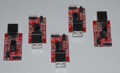
Keywin just bought these local in Shenzhen (cheap) ... He says they worked perfect ... USB-TTL for programming the Infineon.

Keywins-USB-2-TTL.jpg
 
John in CR said:
Back to the windmill thing ...
Well a controller will generate a DC voltage at the +/- power connections (no battery connected) when the hub motor is spinning even when the ignition wire is off.
This is necessary for a direct drive motor to freewheel. The DC voltage at the power connections is directly proportional the the hub rpm.

So if we take a DD hub motor (as our turbine) with a k value of say 10 rpm/v and spin it at 250 rpm ...
then it will create (no more than) ... (250 rpm) / (10 rpm/v) = 25V. This is the BEMF at no-load.
So the turbine must spin at 250 rpm to generate 25V.

And the turbine must spin at 500 rpm to generate 50V.

But lets say we program the LVC=25V and the ignition wire is on.
Then the ignition can be fed power by the motor BEMF.
And we close the ebrake BMS circuit (and the upper regen limit is 60V - stock Infineon)

Then the turbine will now generate 60V at 250 rpm.
It can't go above 60V because the MCU shuts off the regen above 60V.

And ... if you draw current from the turbine (and you maintain the voltage above the LVC=25V)
then you can generate 60V from the turbine at ANY rpm.

EXAMPLE:
BLDC turbine connected to Infineon with LVC=20V connected to 24V battery bank.
ebrake BMS circuit active (no throttle of course).
ANY forward rotation of the turbine will generate charging current.
The amount of current changes at different turbine rpm.

(btw ... there may also be programmed regen algorithms in the Infineon software that "shift" the max regen current)

Hack the R12 circuit to bump the max regen voltage above 60V (like I did on my ride).
 
I posted a question for you on the Regen thread a few days ago conserning the regen current limit on the infinion. I don't want to double-post the question, but wasn't sure in which of these two threads I should put it.

So is the current limit for regular drive the same as for regen, or is there some way to limit it to a lower value? I ask this since my 20Ah Ping has a maximum safe charge current rating of 20A (1C), but my regular drive current limit is set around 40A - two times what I would want to avoid damage to the battery during regen. What's the jist of this situation? I'm sure I'm not the only one wanting to have a regen current limit lower than the drive current limit, since batteries almost always have lower charge current capabilites than their discharge current.


Also, I notice that the configuration software has a "PhaseCurrent" setting, but it is in red... what does this mean? Do I have to play with it to figure out what it does? In theory it should limit the maximum motor current seperatly from the maximum battery current (ie RatedCurrent box).
 
ZapPat said:
So is the current limit for regular drive the same as for regen, or is there some way to limit it to a lower value?
ZP ... Jump to:
http://endless-sphere.com/forums/viewtopic.php?f=2&t=7891&start=60#p129416
http://endless-sphere.com/forums/viewtopic.php?f=2&t=7891&start=60#p129669

Regen "appears to be software regulated and a fraction of the programmed drive current".
I like Level 2 (the highest value) for my DD motor in 26" wheel.
Maybe Level 1 or 0 are better for smaller wheel diameters?

Throttle Regen is turned On or Off in the software.
The Regen Level is also an option in the software.

View attachment 1
Hand eBrake and Throttle Regen only work if BK-GND is jumped.


ZapPat said:
I notice that the configuration software has a "PhaseCurrent" setting, but it is in red... what does this mean?
Oh Sh*t! RED! OMG! (Ha Ha - Red font means nothing).
As a rule of thumb the "Phase Current" should be set at 2.3 x the "Rated Current" (It's a mosfet thing).
 
Looks like we'll have to get Knuckles a CA or something to measure the regen current. :wink:

Any idea what "Converse Speed" means?
Also, do you have a clear idea what the Speed Mode settings do?

Where can I get the programming software? (did you post that somewhere?)

It might be amusing to hack the software so the names of the parameters made more sense.

It might be possible to change the upper voltage limit and a few other things through the software interface with a little hacking.
 
fechter said:
Looks like we'll have to get Knuckles a CA or something to measure the regen current. :wink:
I don't need a CA. My "mental" powers allow me to monitor my regen current telepathically. :wink: :wink:

fechter said:
Any idea what "Converse Speed" means?
It means REVERSE.

fechter said:
Also, do you have a clear idea what the Speed Mode settings do?
Not yet. Geoff and I are still scratching our heads on that. We suspect these values may affect cruise control in some way but we have no definitive answer thus far.

fechter said:
Where can I get the programming software? (did you post that somewhere?)
See ... http://endless-sphere.com/forums/viewtopic.php?f=16&t=7361#p110931

fechter said:
It might be amusing to hack the software so the names of the parameters made more sense.
I already did that. Lil pet project hacking an exe file. What? You don't Chinese English? :roll: I used this free app to hack the exe file ... http://98.131.176.65/endless-sphere/odbg200i.zip

fechter said:
It might be possible to change the upper voltage limit and a few other things through the software interface with a little hacking.
There is no upper voltage limit. There are only limits on the current and the LVC values. Altering the R12 value will "hack" the software pull-down values for LVC and Tolerance. Altering the R44 value will "hack" the software pull-down values for max Rated and Phase currents. (Bump back to http://endless-sphere.com/forums/viewtopic.php?f=2&t=8317&st=0&sk=t&sd=a&start=45#p127913 for a LVC R12 example hack.)
 
OK, I've read this thread, trying to find out a basic fact regarding the Infineon ebrake regen feature. On other regen-capable controllers (e.g. Kelly), there is an external potentiometer that controls the amount of regen braking that occurs. Presumably, this controls the reverse current put back into the battery pack. While there is a programmable braking level that the Infineon evidently allows, my question is:

Is regen braking an all-or-nothing proposition on this controller?

I would like to control the amount of regen by an external pot.

Thanks,

Willie
 
The hand brake regen is an ALL ON regen (although the regen appears to follow a preprogrammed algorithm – the effect is similar to down shifting a manual transmission).
I can stop and go urban riding and never use brake pads at all (except for emergency braking to skid).

The throttle regen is variable. Throttle back a little and you get a little regen. Throttle all the way back to get full regen (same as using the hand brake but throttle regen turns off at 15% WOT and will not bring you to a full stop).

The Infineon controller DOES NOT accept a 5k pot input for any of it’s connections.
(Although I think Geoff57 may have hacked the 5k pot somehow).
 
fechter said:
Also, do you have a clear idea what the Speed Mode settings do?
Not yet. Geoff and I are still scratching our heads on that. We suspect these values may affect cruise control in some way but we have no definitive answer thus far.
cruise control works on using a mometary switch, whatever throttle setting was set when the switch is activated is remembered the switches on the swtichbox can be changed the only way to reset is to re-engauge the throttle, activatethe switch again or press an ebrake.

I have more results on the speed mode settings
i will give the answers but not from top down that will not work
first 3 speed mode: this as normal is badly named the options are switch mode and cycle mode
in switch mode you can use a "switchbox" to control the motor utilising the speed limit, and the speed1, speed2, speed3 and converse speed settings this works with the throttle
cycle mode I think should be renamed to pedelec: the throttle is not required infact ruins the idea of pedelec as the throttle and pedelec system work in conflict the only thing is a sensor at the bottom bracket once the cranks have been turning for 2 seconds the pedelec system kicks in it stops 2 seconds after the cranks stop.

The other settings in this section are all listed as a number this number is a representation of the speed/rpm the motor will go at for a given twist of the throttle the speed 1,2,3 settings have a straight curve if plotted on a graph, Speed limit uses the curve of the 100% setting until the max speed that the setting on any other speed setting would have got it then flattens out so you have maximum tourque but not maximum speed.


fechter said:
It might be possible to change the upper voltage limit and a few other things through the software interface with a little hacking.
There is no upper voltage limit. There are only limits on the current and the LVC values. Altering the R12 value will "hack" the software pull-down values for LVC and Tolerance. Altering the R44 value will "hack" the software pull-down values for max Rated and Phase currents. (Bump back to http://endless-sphere.com/forums/viewtopic.php?f=2&t=8317&st=0&sk=t&sd=a&start=45#p127913 for a LVC R12 example hack.)[/quote]

most things can be reprogramed however the LVC settings leave a lot to be desired and require more options in the software, Regen over 48v or so is going to require pressure put on the board makers xie-chang to change the programming of the Infineon chip before it leaves the factory

Geoff
 
Lets talk some "regular joe" talk.

1st off is there any limit to the current?? In other words if your are in a locked rotor condition will the controller cut out before it sees the massive current load??

2nd is there a source on the board you can borrow 10watts or so (for a fan)??

3rd is there any temp cut offs installed?? So if you overheat the cotroller it turns off??

For us off roaders we need to be able to cool the controller while going only a few miles an hour. I can pull 1800 watts pedal my ass off and only go a couple miles an hour heat builds up fast at 30 amps.
Dan
 
Hallo,
can not get a Max232 based RS232/TTL-Converter going to transfer data to the Controller.
Followed this instruction: Load PC software, load demo file to send to controller and hit "Transmit'. THEN connect the controller.
But no statusbar appeared. How long should I wait?
Echo test in Hyperterminal was ok... (the only thing I know to do in Hyperterminal)

Then I tested transferring data with reversed RXD, TXD. But same failure again.

Is there a nedd to configure the COM-port parameters in Hyperterminal?

May be it´s the software causing problems. Running the Parameter Designer-GUI there were at least MSCOMM32.OCX, Richtx32.ocx, MSCOMCTL.OCX to install to get no more error messages.

any idea?,
Best regards, Georg
 
Whoa, there Georg!

The MAX232 needs to be REMOVED if your cable includes one. The idea is to get TTL-level (0-5V) serial transfer happening. RS232 level (+/-12V) signals, such as come out of the MAX232, will not make your controller happy.

If I'm misunderstanding, and you have modified a cable (like I did) to remove the RS232 drivers - you might want to check the handshaking signals. I grounded DCD, CTS, and DSR pins on the USB-serial converter chip so that any software which might be looking at handshaking will always see the interface as ready. I don't know, for a fact, that this is necessary for the programmer software, but it was for other Windows-based terminal applications...

Edit: Ack. Sorry, Georg - just re-read you post... Looks like you're saying that you've hung a MAX232 on a regular serial port to get an RS232 signal down to TTL... Which is exactly right...

I would go back and revisit what I've just said about handshaking, then. You can either use one of the unused outputs from the MAX232 (the RS232 side) to drive the aforementioned signals to the proper level, or loop back DTR like you would in a 3-wire null-modem implementation. This would mean connecting pins 1, 4, 6, and 8 together...

db9.jpg


If everything is OK, and you test it again with Hyper Terminal, you should (after typing at least one character - I dunno why Hyperterminal does this) see that the lower left status line on Hyperterminal shows "Connected" or "Online" (forget which).

You say you had troubles before copying the support files. It's possible that MSCOMM32.OCX isn't registered properly. To be sure, open a Command window and type "regsvr32 MSCOMM32.OCX". You should get a message saying that the file was registered successfully.
 
geoff57 said:
fechter said:
It might be possible to change the upper voltage limit and a few other things through the software interface with a little hacking.
There is no upper voltage limit. There are only limits on the current and the LVC values. Altering the R12 value will "hack" the software pull-down values for LVC and Tolerance. Altering the R44 value will "hack" the software pull-down values for max Rated and Phase currents. (Bump back to http://endless-sphere.com/forums/viewtopic.php?f=2&t=8317&st=0&sk=t&sd=a&start=45#p127913 for a LVC R12 example hack.)

most things can be reprogramed however the LVC settings leave a lot to be desired and require more options in the software, Regen over 48v or so is going to require pressure put on the board makers xie-chang to change the programming of the Infineon chip before it leaves the factory

Geoff

I'm thinking that the LVC settings as well as the overvoltage limit are numbers that are written to a specific location in the controller's memory. The Infineon software allows you to only write specific values from the drop down list to the LVC spot, and there is no provision for changing the overvoltage limit.

It should be possible to hack the software to change the values listed in the drop down menu to whatever we want (or even allow you to type in a value between certain limits). With a bit more hacking, it might be possible to change the overvoltage setting in the controller if we can figure out the memory location for that parameter.

Anyone have a decompiler program?
 
fechter said:
[...]Anyone have a decompiler program?
It would be soooo much simpler if we could actually have an easy way to give feedback to the controller's designer(s)! If it's as fechter suggests, it would take a couple minutes to just add some values into the comboboxes in the software... :roll:

It's a Visual Basic program BTW, made with VB6 I think. I'm only into compiling, not decompiling so I can't help any.
 
Fishmasterdan said:
1st off is there any limit to the current?? In other words if your are in a locked rotor condition will the controller cut out before it sees the massive current load??
Use a master fuse on the battery (+) to the controller.
Fishmasterdan said:
2nd is there a source on the board you can borrow 10watts or so (for a fan)??
3rd is there any temp cut offs installed?? So if you overheat the cotroller it turns off?
Bump to ... http://endless-sphere.com/forums/viewtopic.php?f=2&t=8587
Thermal Protection
 
ZapPat said:
It would be soooo much simpler if we could actually have an easy way to give feedback to the controller's designer(s)!
LOL^2
:lol: :lol: :lol: :lol: :lol: :lol: :lol: :lol: :lol: :lol: :lol: :lol:

"It is easier for a camel to pass through the eye of a needle than for a rich man to enter the kingdom of God" (Matthew 19:24)

"It is easier to freakin' mod it yourself than to get the Chinese to understand a better way of doing it" (Knuckles 101)
 
Thanks a lot philf, - wow, that was fast.
It is me who is slow.
Looks like you're saying that you've hung a MAX232 on a regular serial port to get an RS232 signal down to TTL... Which is exactly right...
Yes it´s an old school connection, used to talk with an Atmega.
I would go back and revisit what I've just said about handshaking, then. You can ...loop back DTR like you would in a 3-wire null-modem implementation. This would mean connecting pins 1, 4, 6, and 8 together...
Now I have tried that and also another option of connecting pins 1,4,6 and 7,8 seperately. (found it here : http://www.lammertbies.nl/comm/info/RS-232_null_modem.html )
Hyperterminal echo is ok, but sorry to say, it didn´t work out.
It's possible that MSCOMM32.OCX isn't registered properly. To be sure, open a Command window and type "regsvr32 MSCOMM32.OCX". You should get a message saying that the file was registered successfully.
I have choosen the "right click- open with"-option. Then you choose Regsvr32 for registration.

Can´t imagine the trick for now. I`m stumped.
Georg
 
Hmmm, Georg! This is a poser...

It would be useful to have a bit more detail with respect to how you have things hooked up. Sounds like you have a standard serial port connected through a circuit of your own to do the level shift (through the MAX232).

Can you post a pic/schematic of the thing? What is the source of your 5V supply? If you connect your circuit to the controller and measure the voltage while connected, does the 5V supply get pulled down? Have you made any other modifications to the controller, or (particularly), its power supply? Are you attempting to program the controller settings in situ (everything else still connected)? If you attempt the same exercise (load software, open parameter file, select COMM port, hit the transfer button, and then connect to the controller) with nothing else attached, do you get the same result?

It's gotta be something simple :)
 
Hi Guys, been browsing this forum for a while now but finally registered today and this is my first post.

First let me say that this forum is a great source of info and there are obviously some very knowledgable members.
Thanks for all the great info.

I bought a 48v scooter a few weeks ago and am a little disapointed with its performance. I think it may be speed restricted within the programming. It has a 1400W hub motor but I don't think this is being utilized to its full potential so I will be doing some serious modding to it.
I've ordered a new 60V controller from Keywin and am eagerly awaiting delivery. In the meantime I want to see if I can do anything to improve the existing unit. I've attached a photo of the board, anyone recognize it?
I've got the Infineon software working on Vista and am waiting for a TTL interface to arrive.
Is it possible to read the existing configuration from the Infineon controllers?
 

Attachments

  • controller.JPG
    413.6 KB · Views: 3,572
Hiya Mike!

Welcome!

I can't help with identifying what your current controller is, but it's intriguing that there appear to be 15 (!) devices along the rib. Are they all the same? Looks almost like a "3 to 2" scheme for each phase.

You've highlighted a pet peeve of mine with respect to the Infineons, though. You can program 'em, but (unless I'm very badly mistaken), you can't recall the configuration that's in there. I find that bothersome, as it seems you have to load a "known" (to you) config into the things and experiment with the behaviour before you have a starting point. You have no idea how many, if any at all, parameters you changed with the first transfer. It would be sweet to be able to suck the current configuration out play with only the parameters of interest. :-(

Of course, it's possible that the firmware in the controller DOES support this, but the VB program that is currently available to do the programming doesn't bother supporting that feature. I've been tempted to bastardize a data logger onto the interface to see what actually gets sent back and forth between the PC and the controller during programming. Even knowing the bit rate would be a nice starting point, though :-(
 
Thanks philf,
It would be useful to have a bit more detail with respect to how you have things hooked up. Sounds like you have a standard serial port connected through a circuit of your own to do the level shift (through the MAX232).
Yes it is a standard serial port and the level-shifting is done by the SIO-part of this circuit-board: http://www.mikrokopter.de/ucwiki/en/SerCon.
5 Volts are from a DC-powersupply.
If you attempt the same exercise (load software, open parameter file, select COMM port, hit the transfer button, and then connect to the controller) with nothing else attached, do you get the same result?
I did it this way.
Now I have tested the procedure with EB806 and EB812. May be it´s the software.

By the way, I received both controllers from a German dealer two days ago.
He is going to sell the EB806 as a pedelec-regencontroller. He persuaded Ecrazyman to let him sell this controller with software and the V24/RS232 cable. He can do so. His wife is from Shenzhen.

So in the last resort I have to wait another three weeks.
For now I only wanted to lower the controllers LVC, so that I can play with them, without hanging a 11V Lipo in serie with an 32V power-supply.

The pedelec-sensor I obtained is a bipolar Hallsensor with latch. The signal is connected with EB806´s pin "TA". Unfortunately, the controllers motor output is not crank-speed dependent. It´s like full throttle or off.

thanks for help and so long, Georg
 
Hi Phil, thanks for the reply.
Yes there are 15 P75NF75 mosfets. I thought there would be some multiple of 6 so a little confused by that.

Keywin is sending me a 60V 50 amp controller (I will have to add a fifth battery) so hopefully that will do the trick. Are all the controllers he is selling at the moment Infineons?

Also, is there anyway to wire in the high level brake wire? From the item description it only has the two wire brake signal that you shortout to switch the power to the motor off. If necessary I can always wire in a relay to these and use the brake light 12V to trigger it.

Mike.
 
Back
Top