Infineon transistor modification

Hahah... :lol:

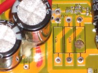
Actually, in all seriousness, that's probably the right idea - a separate thread, I mean. THIS thread *should* stand alone, as the solution you are demonstrating is inexpensive and doable by anyone who can handle a soldering iron. When the final tweaks are done, it should be retained for future reference.

What ZapPat and I are thinking forces the need for a small PCB and soldering SMDs - something that will scare a lot of people away and muddy the waters, here.

Just a thought. I'm up to my ass in my real gig (and real life) right now, so how much I'll pursue the switcher over the next few days, I dunno. But I will make an effort to get an order in to DigiKey today so that I'll have something to play with, should I get some quality time on the weekend.

As a final comment on the simple switcher I have in one of the GM controllers - I made up a couple of the little PCBs when I made it, thinking they'd come in handy. Here's one (identical) to the one on the controller, only with a 5V regulator on it. The coil doesn't have to be that big - it's current rating is excessive - but I happened to have a few of the right value kicking around, so used 'em. This little board fit handily in the space on the GM controller freed up by removing 2 of the linear regulators and the associated caps/resistors (the 5V regulator was left in situ).

SimpleSwitcher.jpg


The thing doesn't really need the heat sink, either. It runs as cool as a cucumber...

Cheers!
Phil
 
I surprised you there, eh Philf?!

Anyways, I'm going to be using this PWM solution in my own controller, but I'll only be revising my PCB to add it in about a month or so. I'll share that part of the circuit with you guys then if philf hasn't already done it.

I'm sure keywin will be happy to integrate this solution into his controller since he hasn't managed to find a switching solution yet himself. I really wonder how things work in China sometimes? Maybe someday I'll go for a visit!

Ciao!
Pat
 
What the buck, eh?

The simple switcher is a good example, but is limited to 60v input max. For this application we don't need 1A of output either (but having extra juice for accessories would be great).

I found something called a LM5009, that can go up to 100v input and has 150ma output. The switch is integrated so all you need is an inductor, diode and capacitor. About $3 from DigiKey. For 150ma, the inductor can be quite small. Downside is these are surface mount only.
http://www.national.com/ds/LM/LM5009.pdf

There are many switching controllers made to drive descrete switches too. One of those may be the cheapest.
 
Heck! The BUCK stops here (engineer's humor). :roll:

But the Infineon pcb has a big bypass capacitor across the LM317 VR (between V(in) and GND).
Any switching regulator mod would need to bypass the LM317 (the LM317 becomes useless).
I would think the output of the switching regulator would need to have smoothing capacitors to reduce AC ripple.

LM317_Cap.jpg
The transistor mod utilizes the LM317 circuit so the overall 12V-15V bus voltage is still smoothed out by the existing cap.
A switching regulator mod would need to somehow use the same cap (if the existing cap is appropriate to squash the output ripple).

Myabe?
 
Yup!

The circuit I had in mind uses a 5008. As ZapPat pointed out, we could just as easily use the cheaper part, as we don't really need 350mA.

For giggles (I *really* should be doing something else), I threw all the parts used in the demo circuit provided in National's application notes into Eagle and had a shot at juggling them around to see how big (small) this thing would be. I better stop myself before I chew up more of my day doing the routing (I want the back side of the board to be a big ground plane/heat sink). The approximate layout was more or less lifted from National's demo board (otherwise I'd still be playing with it :)).

Conceptually, though, it certainly looks promising. I think I'll re-juggle the components so that the board is "squatter", and with the input/output pins in a more meaningful arrangement along one edge. This way, the thing can stand upright in the controller (with silicone along the bottom to eat the vibration)...

LM5008Draft1.jpg


In real life, this layout is about an inch square. There's definitely wiggle room to make it flatter/smaller.

I'd leave the big cap that's currently on the ouput of the 317 in place for additional filtering.
 
Cool Phil (boy, we're really trashing this thread)

It would be good if the swticher board *replaces* the LM317. That means the board layout should have 3 connections that match the configuration of a 317 (input, gnd, output).

If there is a capacitor on the controller board, it might be possible that it could eliminate the need for one on the switcher board.
 
fechter said:
What the buck, eh?
The simple switcher is a good example, but is limited to 60v input max. For this application we don't need 1A of output either (but having extra juice for accessories would be great).
I found something called a LM5009, that can go up to 100v input and has 150ma output. The switch is integrated so all you need is an inductor, diode and capacitor. About $3 from DigiKey. For 150ma, the inductor can be quite small. Downside is these are surface mount only.
http://www.national.com/ds/LM/LM5009.pdf
There are many switching controllers made to drive descrete switches too. One of those may be the cheapest.
Missed the last couple posts, Fechter? :wink:
All three of us seemed to have fallen on the same national semi part... I guess there aren't many other simple solutions available with integrated switches that go up to 100V.
 
We seem to be online at the same time :)

And, yup, trashing the thread (apologies to Geoff and Robert)... Should fechter move all this stuff?

Anyways, the idea is that this little circuit replaces everything from the battery to the output of the 317. The 7805 stays... (Interestingly, one of my boards doesn't have the big T0-220, it has the smaller capacity T0-92). With the 7805 still providing regulation for the MCU and supporing logic, any noise that comes out of the switcher will have little if any impact on the stability of the system.
 
No trashing at all. I am just "Bucking" with you guys! :roll:
(Knuckles like switching regulators :D Knuckles only pawn in game of life)

[youtube]28khv-BydeY[/youtube]

The goal of the thread is the same. Build a (small) black box that spits out 12V to 15V from any input voltage 20V to 90V.

I just chose the easiest way for me to do it (transistor, zeners and resistors) that would fit and I tried to utilized the existing pcb components.

The waste heat (linear solution) is not so much a big deal to me provided it doesn't cause any problems.

And at 72V nominal the heat is only 72-15=57 ... 57 x 0.06 = 3.4 Watts. So the only real advantage of a switching regulator is the heat reduction at 72V.
(unless there is some cost savings or if the switching regulator is more durable than the transistor mod).
 
Hi guys
as Knuckles said this thread was started because I desided the circuit he had designed to allow the Infineon to work with any voltage within reason,and moreover the module's construction and instalation instructions, that I did from his design should be made avalible to everyone.
However there was a second reason if we could prove that there was a viable module circuit board that would do the job we want then we could persuade Keywin to make the module’s himself.
Your ideas on using a LM5009 at the heart of a voltage regulating module are inspiring and more than likely a better solution keep them here, all that can be said on transistor module has been said, if someone wants to copy they can it is easy and requires little skill to duplicate the LM5009 will take skill but needs to stay in the same thread.
As the originator of this thread I say stay here and keep the ideas coming.

Geoff
 
Start with stock Infineon purchased from Keywin ...
(Make sure to ask him about mosfets and capacitors! He has all different combinations these days.)

1) Remove the three power resistors.
Before_Mod.jpg
2) Clean out the holes.
Tight_Fit.jpg
3) Install 680 ohm (3W) in R6 low to the board.
R6_680.jpg
4) Drill a pilot hole in the center of the trace between R01A and R01B.
Pilot_Hole.jpg
5) Drill a larger hole. This will cut the trace between R01A and R01B and allow room for the Transistor circuit zener.
Larger_Hole.jpg
6) Assemble the Transistor circuit.
Assemble_Transistor_Circuit.jpgNOTE:
The 100 ohm resistor will limit the initial current spike when the "ignition" is first turned on.
The 15k resistor can be substituted with any resistor 10k to 20k.
The 36V zener can be less than 5W (the current thru the 36V zener is very small).
The TIP122 is rated for 100V and has 1000x amplification.
The diode is a safety feature to prevent any reverse current thru the transistor.

7) Install the Transistor circuit in R01A. Install another 680 ohm in R01B.
R01A-B.jpg
8)
 
8) Use solder bridges between the V(in) and V(out) of R01A and R01B.
Now the transistor circuit (R01A) is in parallel to the 680 ohm bypass resistor (R01B).

View attachment 5
9) Install a 15V(5W) zener between GND and the 12V(15V) bus.
Connect the 36V(5W) zener from the Transistor circuit to the 12V(15V) bus.

View attachment 4Note:
The 15V zener should be rated at 5W for safety.
This zener will pass significant current (and get warm) if the ignition is connected
to the battery when the peripherals (throttle and motor hall wires) are not connected.
During normal (on-road) operation the 15V zener will not pass any current.

10) OPTIONAL: Now may be a good time to mod R12.
The value of R12 (1200 ohm) affects the LVC AND the Max Regen Voltage.
Adding a resistor in parallel to R12 lowers it's value (in this example R12 becomes 847 ohm).
I like to install (2200+680) 2880 ohm between R12 and GND.

Mod_R12.jpg
11) OPTIONAL: Jumper BK to GND to activate the Regen feature.
View attachment 2
12) SOFTWARE FLASH: Flash the Infineon MCU to desired settings.
The LVC now becomes 20.1 x (1200/847) = 29V
The Max regen now becomes 60 x (1200/847) = 85V

Infineon_Software.jpgNote: The Max regen value can not be changed in the software.

All finished ...
Now the controller will safely accept any battery voltage between 29V and 85V.
It will also regenerative brake and charge the battery between 29V and 85V.


btw ... I started adding a thin sheet of PVC plastic between the bottom of the pcb and the aluminum case.
Just to make sure the Mod circuits don't touch the bottom of the case.
PVC_Sheet.jpg
8)
 
Would 1n4148 be suitable 100v fast switch diode?
If I were to use separate power supply to run the board ( eg. small 12v cell) would it be a simple matter of connect pos/neg to where the regulator is, or more complex?
 
Brett ... You Inspired my new THREAD!
http://endless-sphere.com/forums/viewtopic.php?f=2&t=8610
Bounce there for an ANSWER! :mrgreen:
 
glad I could inspire a 'dummy' thread, will take as a compliment.
reason for going with separate power supply for low voltage board is for a project where I want to isolate high voltage and low voltage parts mainly as its long distance vehicle wanting to make reliable as possible. Just reducing 'potential' probs. Hoping also to have fets separate to the main board for easy replacement on the run.
 
solarbbq2003 said:
glad I could inspire a 'dummy' thread, will take as a compliment.
reason for going with separate power supply for low voltage board is for a project where I want to isolate high voltage and low voltage parts mainly as its long distance vehicle wanting to make reliable as possible. Just reducing 'potential' probs. Hoping also to have fets separate to the main board for easy replacement on the run.
I hear what you are saying (and glad you have a sense of humor). AND ... Your logic is perfectly sound.
A separate (constant voltage) power supply for the controller "ignition" circuit will GUARANTEE that the ignition is always functional.
It will then run any MAIN POWER voltage to the mosfets.
 
Hi Knuckles,

Very useful thread. Just one question. You decribe how the controller limits the regen to 60 volts and also how to increase this to 85 volt. Does the controller know the correct voltage to charge the battery at or does it simply try to push it to the max voltage? So if I have 5 SLAs (60v) is it going to charge these at 85volt which would be too high?

Mike
 
Mike1 said:
Does the controller know the correct voltage to charge the battery at or does it simply try to push it to the max voltage?
The Infineon controller "tries" to reach the max regen voltage but is current limited by a preprogrammed algorithm.
If the system voltage EXCEEDS the max regen voltage then regen is disabled (it slips).

The practical application of regenerative braking is that it is an electrical braking system (EBS) and not really a battery charging system. Yes braking energy must go somewhere (like heating the brake pads and rim or as electrical energy going back to the battery).

Of course there is always the proverbial "start at the top of a very big hill with bats at 100% SOC then intentionally regen brake down the long hill and overcharge your bats”.

The reality is that this rarely (if ever) happens in the real world.

Riding your EV consumes energy to overcome friction (rolling and air resistance).

Within the first few miles (or less) of riding a fully charged battery the battery will drop down to it’s nominal voltage.

Regen braking is also typically a short-term event compared to using energy to propel the EV. And the braking current needed is only a fraction of the drive current consumed.

I prefer to think in terms of regen voltage as compared to regen current. Mainly because different battery chemistries behave differently to reverse (charging) current.

Example 1 – SLA: The size (in Amp-hrs) of each 12V battery, the SOC and the # of 12V batteries affect the charging rate (amps) at a given voltage. SLA can discharge at very high amps but can only accept a very low charge current. As you try to charge SLA at high currents the voltage will rise rapidly. A good rule of thumb for SLA is that the charge voltage for a 12V battery should never exceed 15 volts.

For a 5 battery nominal system (5 x 12V = 60V) the max charging voltage should never exceed 5 x 15V = 75V. OTOH … the braking energy is V x A = W. So as the regen brake voltage goes up less current is needed to brake (slow down) the EV.

Example 2 – LiFePO4 (a123): A123 can discharge at very high amps AND can ALSO accept a very large charge current. Charging A123 at high currents does not cause the voltage to rise rapidly (until they approach 100% SOC then the voltage will skyrocket).

A123 tops off at about 3.7 volts per cell. So for 4 a123 cells (12V nominal) the max charging voltage should not exceed (4 x 3.7 = 14.8V). The a123 can accept much more charging current (at a lower voltage) than the SLA during charging but the max CHARGING voltage of the two battery systems is about the same.

In theory, regen braking voltages should be limited according to the battery in use on the EV.
24V battery … Max charge voltage = 30V.
36V battery … Max charge voltage = 45V.
48V battery … Max charge voltage = 60V (default Infineon value).
60V battery … Max charge voltage = 75V.
72V battery … Max charge voltage = 90V.
(Note that regen braking is disabled by the processor over the max charge voltage.)

In reality, it is virtually impossible to overcharge batteries using regen braking in the real world.
And, of course, ONLY mechanical brakes can make your tires skid to a stop.

Bottom line regenerative braking is cool and saves on brake pad and rim wear.
It will also (slightly) extend ride range and allows for a potential to brake-by-wire (this could be handy).
It may also allow for better battery health (for SLA) as reverse current pulses appear to extend bat life.

The coolest potential is for regen at a standstill. Imagine the ebike on a nice sturdy kickstand with rear regen wheel off the ground.
Pedal in place and charge your bats (and lose 20 lbs of body fat in the process).
Good to have if the “Grid” goes down.
 
Thanks Knuckles,

I'm going to do the R12 mod and use a switch on the BK jumper, sometimes its useful to be able to freewheel. Is the BK jumper just a setting for the processor or does any real current flow through it? This will determine what switch and gauge of wire I use.

Mike.
 
Mike1 said:
Thanks Knuckles,

I'm going to do the R12 mod and use a switch on the BK jumper, sometimes its useful to be able to freewheel. Is the BK jumper just a setting for the processor or does any real current flow through it? This will determine what switch and gauge of wire I use.

Mike.
hi mike
just use any switch you have there is no current to speak of, I just go to my "small switch" tub and grab one out for any of the options on the infineon that need a pad jumpered to GND to activate.
Geoff
 
man you guys get two thumbs up for the great work you've done on controllers. I cant believe how much the controller has advanced in the past year with the help of knuckles , fletcher and others . GOOD JOB and thanks from me
 
Haven't had much time to get back to this thread since I last posted about the switching experiment. Actually, what time I have been spending in the e-bike world, I've been spending on something *else* which will interest quite a few people here - but that's a whole other story and a subject for a whole other thread when I'm far enough along :)

Anyways, I had a couple of other projects which were ready for prototype PCB boards and realized that the switcher circuit was pretty small - so why not finish the routing job and etch a couple while I was at it. After buggering around with the layout to get it to fit a certain target size (took me about an hour and a half to route this handful of parts - even with a reference design as a guide!), I got to where I wanted to be. Hell, they're so small, I got TWO on a piece of scrap board that was going into the garbage.

This is a double-sided board - it'll have 4 manual "through-plates" when it is done, but the back is mostly a giant ground plane/heat sink with one trace on it. Not very interesting.

5008%20psu.jpg


I've got some other stuff to kill off before I can get back to this - but I hope to populate it and test it over the next week. I can probably get it running tomorrow, but actually installing it in a controller and going for a ride with it will take me into next weekend.

My big phat thumb doesn't give you a sense of scale. The layout is just a little less than the width of a quarter!

I dunno why I'm so dubious about this thing - it's just too damned SMALL to be a power supply. I wouldn't even have thought of doing something like this, were it not for the existence of the aforementioned reference design, and the fact that there is a real (working) demo board based on that design... though it's comparatively huge.

Maybe this should a be game show... "Smoke or No Smoke, with your host PhilF"...

Get that guinea pig ready, fechter!
 
hi phil
what is the orintation for the board is i presume the four large pads will match with four pads on the main board originaly for resistors.
be good to see how it works out.
Geoff
 
Hey, Geoff :). Had to go back and look at my original comments - I suck at differentiating between the voices in my head and my "out loud" voice.

Yes, I did say that I was going to consider re-organizing the pin-out of the finished unit to be more alignment-friendly with the existing PCB layout on the Infineon-based Shenzhens - but when I got into the exercise of actually doing the component re-arrangement and routing, I realized that this would be a self-defeating design decision. (Edit: Bugger me, I think that's the heaviest use of hyphens I've used in a single short sentence in my entire life, critiquing a Hemmingway "paragraph" notwithstanding). Aside from the fact that the controllers we're talking about in this thread have undergone at least one "real-estate" revision of the power supply section since Knuckles posted the first PRoN pics - I've since acquired others that could also benefit from a switcher - and they're radically different in layout. I realized (in the routing/arrangement process) that accommodating any SINGLE board layout was a waste of time. Honestly, when I populate one of these puppies and go to test it, it will be with one of my hacked earlier Shenzhen controllers (as supplied by Golden Motor, and which *is* the controller that was the basis of the first PIC-based 72V e-crazyman). It's not even remotely similar in PS layout to the Infineon Shenzhens.

Anyway, being so small, the board will either sit flat in the area that becomes a void as result of all of the heat-generating linear devices it replaces, or can stand up (and still slide into the case without collision). Mechanically, I'll just do what I always do - WIRE the thing and stick it down with high-heat silicone. If I need to service anything, I just "peel" it off :) Works for me!

But - to keep it all in perspective - I *still* have my reservations about the outcome. This is the first "power supply" I've ever seen that directly passes its output through an MSOP8 package. If this was such a slam-dunk, why didn't the frikkin' controller come this way in the first place?

Oh. Cost. Yeah, in 1000+ quantities, the chips are about $2 (US) each. And then there's the pesky inductor and all of the other stuff that goes around a circuit like this. Doesn't make good business sense, when you're selling something that merely has to attain a singular spec (24, 36, 48V usually). Most people would care less... Except us :twisted:
 
fried_guinea_pig.jpg

There you go!

But - to keep it all in perspective - I *still* have my reservations about the outcome. This is the first "power supply" I've ever seen that directly passes its output through an MSOP8 package. If this was such a slam-dunk, why didn't the frikkin' controller come this way in the first place?

Sometimes they don't think outside the box. Cost could be an issue, but they can get knock-off versions of the switcher chip too. They'll see this and you'll find them in controllers by next year.

That MSOP8 is a tiny looking little sucker. It would be well suited to being assembled by machines. What did you find for an inductor? Those things cost more than the chip usually.
 
Back
Top