
You are using an out of date browser. It may not display this or other websites correctly.
You should upgrade or use an alternative browser.
You should upgrade or use an alternative browser.
Infineon XC846 72V 45 Amp Controller
- Thread starter Knuckles
- Start date
hi I have enough controlers here to do tests on to see if i can do something about this problem as there are a lot of "soft start" controllers out there that need the "soft start" removing there has already been some ideas on docs 18 fet thread as discribed above i will try them when i have some time free.swbluto said:Does anyone have an idea what resistor/capacitor on the current model of the infineon implements the soft-start throttle ramp? Apparently some do not like this soft-start "feature" as it hinders wheelies and causes traffic-critical problems.
with all of the talk there has been around about the soft start not being liked I decided to have a word with keywin, I was on skype chat with him for over 2 hours included in the talk was thaty we want hard start infineons, he has promised to get 50 12 fet boards in stock of the "hard start"type they will be the same as the infineon 12 fet controllers sold at the moment there will just be no time delay on the throttle knuckles can have his old "sawblade of death" as he called his front wheel spinning on throttle up.
Geoff
Jeremy Harris
100 MW
Geoff,
Did you manage to find out from Keywin if the firmware in our existing soft start controllers can be re-programmed?
This should be possible, I believe, we just need to find out how to do it.
Jeremy
Did you manage to find out from Keywin if the firmware in our existing soft start controllers can be re-programmed?
This should be possible, I believe, we just need to find out how to do it.
Jeremy
GGoodrum
1 MW
Yes, I'm with Jeremy. We need an answer from him on whether existing 12 FET and 18 FET boards can be re-flashed with the new code. Also, why not just make this one of the programmable features?
-- Gary
-- Gary
GGoodrum said:Also, why not just make this one of the programmable features?
That's definitely easy to do, so I don't see a reason why it couldn't be done.
ZapPat
10 kW
It's either part of the ROM firmware, or might be kept in the EEPROM but the PC programming interface doesn't include the option. Either way good luck getting this changed because I don't think keywin has any control over the source code, including the PC programming software's. Many vendors seem to have various versions of this controller design, but I wonder who actually created the thing in the first place?swbluto said:That's definitely easy to do, so I don't see a reason why it couldn't be done.GGoodrum said:Also, why not just make this one of the programmable features?
ZapPat said:... I wonder who actually created the thing in the first place?
According to the infamous Powerpoint presentation around the net that describes the Infineon XC846 controller, it was designed by http://www.sletech.com, in all likelihood. They do list an email contact (vincent@sletech.com). Anyone (preferably a Chinese speaker) want to talk to Vincent? It is correct that the "soft start" (mis)feature is almost certainly a firmware feature, and frankly should be able to be modified in the standard control panel programmer.
Edit: As I have since found out, the controllers that Keywin and others are currently shipping come from Xie-Chang (how's your Chinese?)
Hi
I have downloaded the parameter designer and copyied files to system 32 folder and still can't get the program working, are ther different files for vista?
Has anyone made any progress with the amp limit feature of the software yet?
Thanks for al the great information my e-bike is nearly ready to go after lurking on the forum for six moths.
HI I have the 36V controller from WE I have scraped most of the darn rubber off the board but I can't fine specs for it it is Board# EB712XC. it has a daughter board in place of hall sensors from the motor outputs A,B,C to the hall in SA,SB,SC I was wonderig if this is compatible with the mods you all are making to the 812 board. I would like to enable regen on this board.
The board uses IPB120N06N MOSFET chips.
I am able to run the board at 48V and get about 30-32MPH on the standard WE hub moter with 26" tire. I'd like to increase the voltage more and see what it can do. but don't know if I will fry the board.
Thanks,
LeX
The board uses IPB120N06N MOSFET chips.
I am able to run the board at 48V and get about 30-32MPH on the standard WE hub moter with 26" tire. I'd like to increase the voltage more and see what it can do. but don't know if I will fry the board.
Thanks,
LeX
Attachments
richerson said:Hi
I have downloaded the parameter designer and copyied files to system 32 folder and still can't get the program working, are ther different files for vista?
Has anyone made any progress with the amp limit feature of the software yet?
Thanks for al the great information my e-bike is nearly ready to go after lurking on the forum for six moths.
To get it to run in Vista right click on it and select "Run as administrator" I had the same problem.
richerson said:I have downloaded the parameter designer and copyied files to system 32 folder and still can't get the program working, are ther different files for vista?
I just got my Xie-Chang EB812XC-A-B controller (AKA the latest version of the Infineon XC846 72V/45A controller) programmed today, and I thought that I would go over some of the details. I used a Win XP laptop, so the details (especially permissions) may be different on Vista. This mini-guide may help, if you are trying to get started.
1) If you are using a USB-COM cable like I am, you will need a driver for it. This driver works with the cable that Keywin is currently shipping: Prolific USB-Serial Driver You will need to install this and enter the COM port in the Parameter Designer window.
2) You may need some ActiveX files that need to be activated before the Parameter Designer will run. Here are the ones that I activated:
View attachment SystemActiveXFiles.zip
To get these to work, open up a windows command prompt window (CMD shell), change directory to where the zip has been unpacked (this should be a subdirectory of where you keep the Parameter Designer application) and run the following command from the prompt, e.g.:
regsvr32 COMDLG32.OCX
regsvr32 MSCOMCTL.OCX
and so on for the ActiveX files you need to activate. You will need to run these in a privileged/elevated shell on Vista. I suspect that if you simply put all the *.OCX files in windows\system32, these probably get run automagically, but hey, I'm no WIN32 expert.
3) OK, so now you have the Xiechang/Infineon Parameter Designer program working - that is, when you double click on it, it boots up this window:

There are posts in other threads that discuss, somewhat incompletely, what all the parameters are. It will be part research, part trial-and-error to get the numbers right. You are on your own for now, but I hope to improve the guide that currently exists on parameters.
You still have to run a flash session to make it all work. The microcontroller on the Xiechang controller boards (e.g. the Infineon XC846) is programmed when the controller is unconnected from its normal power source. So unplug the battery pack if it isn't already.
There are 4 wires ( power = red, ground = black, data+ and data- ) that connect to the board. You will want to put a momentary contact, normally open, SPST switch on the red wire between the computer and the controller board.
Enter the parameters that you want to use into the Parameter Designer window. I cannot help you here, yet, I'm still sorting this stuff out.
It is finally time to rock and roll!
A) Click on the Start Transmit button in Parameter Designer - nothing will happen, yet.
B) Click on the N/O SPST switch on the power wire of the data cable and hold it closed.
C) Watch the progress bar and the new parameters are flashed into the XC846 - this only takes a few seconds.
D) Release the switch - you have programmed your controller!
Fun!
I hope that this was helpful to someone.dnmun
1 PW
thanks, i look forward to reading your comments on the parameters too. i am back to running w2000 on an old laptop because my XP laptop crashed. would i run these sequences in cmd prompt then?
thanks again
thanks again
I'm pretty sure that the commands are the same in W2K. But as I said, YMMV, since I am not a WIN32 guru. I'm not afraid to experiment, however :wink:dnmun said:i am back to running w2000 on an old laptop because my XP laptop crashed. would i run these sequences in cmd prompt then?
Hey guys. I've long been reading here and figured today it was high time I actually became a member. After reading everything I could find I decided to buy a 72V 45A controller from Keywin (e-crazyman). Took what seemed like forever to get to me but was well worth the wait. Man this thing is GREAT! Just ahh...
From the beginning when I hit a bump I'd hear the electronic "thunk" from my motor like the key had been switched off while I was going.
Then after awhile when I hit a small bump it'd do that, but sometimes if I hit a big one it'd make the sound and loose power for a sec, then it'd smoothly come back as if I'd let go of the throttle and then grabbed it again.
Now just the little bit of vibration from the motor is enough to do it I guess and sometimes it stays off... and I'm not sure if it's time or smacking the controller that gets it to come back. This does seem to happen after it's warmed up a bit and yes, it's got plenty of air flow and even a 12v fan that I installed on the end blowing across the FET side to help keep in cooler in the 105 degree summer I'm expecting here
HELP!! PLEASE!!! I've opened it up to search for a weak feeling wire, checked all the solder joints that are big enough for a naked eye, rode with the meter attached to the big and small vcc wires at the controller connector (they don't seem to change at all when this happens, except for the increase since there's no load on the batts) haven't checked power to the hall sensors yet but will tomorrow..
Any ideas on what I should look at/for?
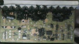
Okay guys, here's an update.. wish I'd read the number off the board but I have the controller with two 100v caps standing up next to the big power resistors that feed the regulators...
Found the problem that was making it shut off!
R11 was bad or not making a good connection. Luckily since it was as bad as it was I was able to have the case open, everything hooked up, and tapped it till it shut off in the garage, then I could run around the board with my tester and yep, there it was! 0.1v signal into the voltage sense input.
I have some spare parts in there now that get a 5.5v signal going out but don't have any clue what the LVC will be.. dangerous.. must be VERY careful!! Have a few blackened boards to upload pictures of already and only 2 spare mosfets
I know R12 is 1.2k ohm and R10 I think measured 7.7k ohm..
Anyone (Knuckles?) know what the values of the other components in the circuit are?
Was considering the transistor mod so I could connect my batteries in parallel for some serious range instead of speed at times so hell, what do you think?
solarbbq2003
10 kW
- Joined
- Apr 7, 2007
- Messages
- 500
anyone looked into the 'self learning' function in the infineon chip, makes easier to match the controller to an unknown motor to get wiring combination correct, the chip has the function built in but no idea which pins need shorting or other method to make it work. Other self learning controllers you just connect to wires together when using with a new motor, then disconnect when have the right combination ( dont have to change hall sensor wire combos just the phase wire combo to get smooth running, means not having to go through the 36 different combos)
dnmun
1 PW
sbar- you are asking what are the values of the resistors in the voltage divider between Vcc and ground in the LVC bridge? if the surface mount resistor was loose, why can't you just solder it back in place? i had some open yesterday and just saw this after i closed them back up, but drbass has very good closeups in the 18FET infineon thread and you may be able to read the values off his pictures. measuring the resistance is not gonna work when there is an active device in the bridge, the input to the 846.
solarbbq2003
10 kW
- Joined
- Apr 7, 2007
- Messages
- 500
sent you an email lame
seems SL pin on the controller is self learn pin, power off connect to gnd, its in self learn mode, hall sensor connections just colour for colour is ok ( not important how the hall wires are connected , except black/red of course), if motor doesn't run corectly ( smoothly), then power off, swap two thick phase wires, power on with SL to gnd, motor should run smooth ( if not change thick phase wires again after power off). Once running smooth disconnect SL to gnd, it will remember the setting, then power off..........use to match the controller to a motor where not sure how the halls and phase wires connect.
seems SL pin on the controller is self learn pin, power off connect to gnd, its in self learn mode, hall sensor connections just colour for colour is ok ( not important how the hall wires are connected , except black/red of course), if motor doesn't run corectly ( smoothly), then power off, swap two thick phase wires, power on with SL to gnd, motor should run smooth ( if not change thick phase wires again after power off). Once running smooth disconnect SL to gnd, it will remember the setting, then power off..........use to match the controller to a motor where not sure how the halls and phase wires connect.
solarbbq2003
10 kW
- Joined
- Apr 7, 2007
- Messages
- 500
cancel that previous post, SL is speed limiter, whoops, theres some way to do it, read somewhere the chip has self learn function, sorry
sl is the correct pad to ground to put in self learn mode BUT the controller must be a self learning controller.solarbbq2003 said:cancel that previous post, SL is speed limiter, whoops, theres some way to do it, read somewhere the chip has self learn function, sorry
depending on the model the chip is programmed so SL is a self learn switch or a speed limit switch both types of controller are avalible.
Geoff
Oh man, you guys kick it, thanks! Yeah the resistor that I pieced in there is about 110k and not really working the controller still runs fine, just I have no LVC as of right now.
I tried to solder it back down but couldn't get it to make a connection? Even after taking it off the board and trying to measure directly across the resistor itself I couldn't get anything. Guess it was the resistor itself that came apart internally or something.
The things are so tiny it's hard to tell!!
One other question since I don't yet have the cable or software to flash this thing like I want to.. If I do Knuckles' transistor mod am I limited to the 84v max operating voltage that he seemed to claim in his how to? Seems to me that as long as the control section of the board is fed it's proper 5 and 15v if could safely be a bit higher? And, I can still adjust the LVC by changing the value of R12 right? Just can't regen (yet)?
Thanks again guys! And my blown up stuff pics are coming soon!
Steve
the controller still runs fine, just I have no LVC as of right now.I tried to solder it back down but couldn't get it to make a connection? Even after taking it off the board and trying to measure directly across the resistor itself I couldn't get anything. Guess it was the resistor itself that came apart internally or something.
The things are so tiny it's hard to tell!!
One other question since I don't yet have the cable or software to flash this thing like I want to.. If I do Knuckles' transistor mod am I limited to the 84v max operating voltage that he seemed to claim in his how to? Seems to me that as long as the control section of the board is fed it's proper 5 and 15v if could safely be a bit higher? And, I can still adjust the LVC by changing the value of R12 right? Just can't regen (yet)?
Thanks again guys! And my blown up stuff pics are coming soon!
Steve
dnmun
1 PW
so you lifted one of the surface mount resistors in the voltage divider bridge for the LVC input to the 846? but it works? be careful you don't put a high voltage into the processor, the Vcc needs to be sunk to grd and the trace going off to the processor should be really low voltage.
i lifted that cap when i put 1/4W resistor in parallel the last time, too long with the soldering iron and it stuck in the solder on the tip, lucky i was able to hold it down in place and solder it back up without shorting it.
i lifted that cap when i put 1/4W resistor in parallel the last time, too long with the soldering iron and it stuck in the solder on the tip, lucky i was able to hold it down in place and solder it back up without shorting it.
Similar threads
- Replies
- 5
- Views
- 3,385
- Replies
- 9
- Views
- 1,678
- Replies
- 8
- Views
- 7,117
- Replies
- 12
- Views
- 5,851