Knuckles
10 kW
Well I now have it and I like it.
And I have been testing it and (of course) dissecting it.
Basic Specs: (12) irfb4310 mosfets, Infineon XC846 microprocessor, LM317 Voltage regulation, 45 amp shunt settings.
btw ... The caps are glued to the pcb (fechter's recommendation)! Nice touch. Good to see that they (our Chinese friends) are listening to us!
One problem I have is that my motors won't pull anywhere near 45 amps.
The controller does make my best motors "take off" like SOBs and that is nice!
But at top speed I am still pulling under 30 amps (need to find some hills or a 'dirtdad' type trailer to pull).
Another problem I have is I don't have a PUMA/BMC to test it at 72V.
To me this is most critical as it is the primary reason for using this new MCU pcb.
This controller should run the PUMA/BMC flawlessly. Mark in UK is testing it now at 36V and 48V.
But I want to see the PUMA SCREAMING at 72V (ALWAYS check your motor for heating at these "ludicrous speed" settings)!
So here come some pics ... A quick glimpse "Out of the Box" ...

The first thing I noticed after plugging it in was that the controller was HOT!
Even when only using the orange wire to + of my charger PSU. Turns out the orange wire was drawing 130mA at 84V! Yikes! Why so much?
So I found out why. The VR power resistors were a total of 500 ohm. Big GOOF! The controller was generating 84V x 0.13A = 11 Watts of heat!
A little bit of V=IR math and I bumped them up to 800 ohm.
Now the max orange wire current is 70mA at 84V (and still 60mA at the LVC of 59V).
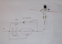
Here are the before and after pics of the power resistor "tweak".
The original resistor setup (left resistor is 300 ohm and right resistor is 200 ohm).

My mod moved the 300 ohm over and I added (3) - 1W 100 ohm resistors.

What is interesting is that the far right resistor actually bridges the LM317 input and output pins.
This has the effect (with other circuitry) of clamping a constant 15.5V for use by the controller.
60mA appears to be plenty to do this. Anything more than 60mA just generates excess wasteful heat.
For my 72V system, these extra resistors made it run so much cooler.
You may notice that 300 ohm resistor got a little toasty before the tweak!
Even at 800 ohm total all these resistors are way hot to the touch.
But now well within rated watt limits.
btw It would be kind of neat to use this "wasted" energy to run LED lights or something else. Just a thought.
And I have been testing it and (of course) dissecting it.
Basic Specs: (12) irfb4310 mosfets, Infineon XC846 microprocessor, LM317 Voltage regulation, 45 amp shunt settings.
btw ... The caps are glued to the pcb (fechter's recommendation)! Nice touch. Good to see that they (our Chinese friends) are listening to us!
One problem I have is that my motors won't pull anywhere near 45 amps.
The controller does make my best motors "take off" like SOBs and that is nice!
But at top speed I am still pulling under 30 amps (need to find some hills or a 'dirtdad' type trailer to pull).
Another problem I have is I don't have a PUMA/BMC to test it at 72V.
To me this is most critical as it is the primary reason for using this new MCU pcb.
This controller should run the PUMA/BMC flawlessly. Mark in UK is testing it now at 36V and 48V.
But I want to see the PUMA SCREAMING at 72V (ALWAYS check your motor for heating at these "ludicrous speed" settings)!
So here come some pics ... A quick glimpse "Out of the Box" ...
The first thing I noticed after plugging it in was that the controller was HOT!
Even when only using the orange wire to + of my charger PSU. Turns out the orange wire was drawing 130mA at 84V! Yikes! Why so much?
So I found out why. The VR power resistors were a total of 500 ohm. Big GOOF! The controller was generating 84V x 0.13A = 11 Watts of heat!
A little bit of V=IR math and I bumped them up to 800 ohm.
Now the max orange wire current is 70mA at 84V (and still 60mA at the LVC of 59V).
Here are the before and after pics of the power resistor "tweak".
The original resistor setup (left resistor is 300 ohm and right resistor is 200 ohm).
My mod moved the 300 ohm over and I added (3) - 1W 100 ohm resistors.
What is interesting is that the far right resistor actually bridges the LM317 input and output pins.
This has the effect (with other circuitry) of clamping a constant 15.5V for use by the controller.
60mA appears to be plenty to do this. Anything more than 60mA just generates excess wasteful heat.
For my 72V system, these extra resistors made it run so much cooler.
You may notice that 300 ohm resistor got a little toasty before the tweak!
Even at 800 ohm total all these resistors are way hot to the touch.
But now well within rated watt limits.
btw It would be kind of neat to use this "wasted" energy to run LED lights or something else. Just a thought.