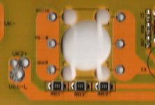
Instant Start 18 fet Infineon Boards are here...

Guys..

You know what...?.. kapton tape is the first thing i wanted to put on the board to protect the case on the first soft start version whne i saw the board... and ... on this one.. i just forgot... I have already kapton in my lab..... I just forgot... :roll:

I had a great news fron Kenny... He will send me a new controller with new mosfet IR... for free since the one i received was with the fake mosfets..

Watta nice Crystalyte customers service! :mrgreen: Thanks Kenny!

That will make me a second backup controller

now my 18 mosfet controller board inventory: 5x ... lol

I hope having ONE working fine for what we still WANT.. 150A 100V NO PROB !

Doc
 
Doctorbass said:
I had a great news fron Kenny... He will send me a new controller with new mosfet IR... for free since the one i received was with the fake mosfets..

That is really good news Doc. Glad to hear that Kenny is following in the footsteps of Kelly.
Sure he may lose out on $80 by sending you that controller, but he will probably make $8k more in new sales by the good publicity. :wink:
The only reason I was willing to pay $700 for the Kelley was because I heard that they had excellent customer service with a no questions asked replacement policy.
Now that I hear Kenny stands behind what he sells that gives me more confidence for the large order I am contemplating.

Keywin has gone silent so... Unless I find out he is in a full body cast in Cuba I don't think I can feel confident enough to place another order through him.

I discussed an order with Kenny for 50 units built to my specification and he was interested.
He can turn around a sample unit in 3 days so after we work the last of these bugs out I may order a sample.
He still does a few things that I feel are a little klugey, but he is getting better every day, and he will build to spec.
His price was not stellar, but definitely good enough to be considered.

-methods
 
Doctorbass said:
I hope having ONE working fine for what we still WANT.. 150A 100V NO PROB !

I will be really surprised if you can even get your 5305 to draw that much current... When I was running with no current limit I could barely get it to pull a consistent 110A @ 88V after the first few seconds. I guess if you are running a 5304 or some other higher KV setup that should not be hard at all though. :eek:

I think the heat from the internal resistance of the mosfets will be trivial even at 150A. The real heat in the system is going to be from all that nasty flyback shooting through the internal diodes. You are going to see some incredible loads for the first few seconds. It will be interesting to see how the controller behaves when you are able to load it down to a constant 150A for 15 seconds. I am nearly positive that heat wont be an issue on that time scale though... Your motor is going to eat itself alive after about 10 seconds of 150A :mrgreen:

Better bring something to cool the motor with between runs.
Have any big Peltier devices around?

-methods
 
methods said:
Doctorbass said:
I hope having ONE working fine for what we still WANT.. 150A 100V NO PROB !

I will be really surprised if you can even get your 5305 to draw that much current... When I was running with no current limit I could barely get it to pull a consistent 110A @ 88V after the first few seconds. I guess if you are running a 5304 or some other higher KV setup that should not be hard at all though. :eek:

I think the heat from the internal resistance of the mosfets will be trivial even at 150A. The real heat in the system is going to be from all that nasty flyback shooting through the internal diodes. You are going to see some incredible loads for the first few seconds. It will be interesting to see how the controller behaves when you are able to load it down to a constant 150A for 15 seconds. I am nearly positive that heat wont be an issue on that time scale though... Your motor is going to eat itself alive after about 10 seconds of 150A :mrgreen:

Better bring something to cool the motor with between runs.
Have any big Peltier devices around?

-methods

I have a 3 x 3 pelletier.. but that draw too much current for the heat produced at that rate..

The motor i'll use is the 5302 :twisted: .. and IT CAN DRAW alot of current!

So the kV problem is solved.. I still have a 5303 on a 20" wheel too in backup ready to swap in case where the max speed would draw to much current and that i need to go with lower kv..

here is my last no load speed test http://www.youtube.com/watch?v=_0lQOBhLG68

I expect something like 2/3 of the speed in real conditions..

Doc
 
why not carry a small yard sprayer filled with water to the track and use it to spray down the motor immediately when you clear the trap at the end.

cooling the magnets and the adhesive which holds them in place is something to worry about too. spraying the hub with water will cool the outside immediately and if the insides are still hot hot, the chances of water getting to the hall sensors is slight, especially since kenny put the new seals in too.

CO2 fire extinguishers might be a little global warming insensitive, but it would help, but i think water could carry away more heat. jmho.
 
No worri about heat on the motor guys!

I thought about that.. 8)

i drilled 16 5/8 holes on the side covers of the motor and i bought an air pump to inflat camping bed.. at 12V i have alot of CFM !!

I tested it and to cool down the motor from 100 degree to 30 degree it take 5 minutes :mrgreen:

now let's return to the controller subject! :wink:

Doc
 
hi
with that thick bus you fitted on the board you may have problems with a short between the bottom of the board and the case as well as the edgeknuckles puts a thin sheet of plastic in there to act as insulation, he did this after one batch of ready built controllers came from keywin almost falling out of the slot you are worried will cause a short now we both add a sheet as standard.

Geoff
 
Doctorbass said:
So the kV problem is solved.. I still have a 5303 on a 20" wheel too in backup ready to swap in case where the max speed would draw to much current and that i need to go with lower kv..
here is my last no load speed test http://www.youtube.com/watch?v=_0lQOBhLG68
I expect something like 2/3 of the speed in real conditions..
Doc

(My thread, I get to go off topic :mrgreen: )

I am sure you have given this a lot of thought Doc. . .

My gut feeling is that you will not get enough thrust from a 5302 off the line.
Even a 5305 is somewhat slow out of the hole at 100V 150A in a 24" wheel in my experience. Does not even force a wheelie or break traction.
A 5302 will have much, much less torque at 100V 150A near stall speed.
You may be able to reach a higher theoretical top speed but I think the acceleration will be too slow to reach it in the 1/4th mile.

It is a little late, but I think the way to do it is to run a 5305 and 200V
Then you get the thrust AND the speed AND the power 8)

-methods
 
Warning! OT post!
... forgive me please. My "problems" with EVs (their modern re-introduction) are all social and political which makes the tech challenge small change... but anyway...

This is a great thread. An international (controller) murder-mystery. Real Holmesian/Bond stuff... Just casting the actors - Patrick stands out as Daniel Craig (recently voted as the lollypop most wish to lick, so Mrs.Methods will have to attend the shoots) and DocBass as Dr.Evil (though not evil at all and actually part of the A Team) with His choice of Mini-Me... (lyen... ya gotta audition! Ya could steal the show?) With an international cast of characters as Gary and...and... too many to name. Now looking for an ES denizen who is a script writer in the meat world? PM me! We're looking at a Rocky Horror Classic here. The residuals will be huge!
:lol:
tks
LOck

ps... Just another example why many ES threads need to be preserved for posterity (see "Epic Topic Nominations")
 
methods said:
Doctorbass said:
So the kV problem is solved.. I still have a 5303 on a 20" wheel too in backup ready to swap in case where the max speed would draw to much current and that i need to go with lower kv..
here is my last no load speed test http://www.youtube.com/watch?v=_0lQOBhLG68
I expect something like 2/3 of the speed in real conditions..
Doc

(My thread, I get to go off topic :mrgreen: )

I am sure you have given this a lot of thought Doc. . .

My gut feeling is that you will not get enough thrust from a 5302 off the line.
Even a 5305 is somewhat slow out of the hole at 100V 150A in a 24" wheel in my experience. Does not even force a wheelie or break traction.
A 5302 will have much, much less torque at 100V 150A near stall speed.
You may be able to reach a higher theoretical top speed but I think the acceleration will be too slow to reach it in the 1/4th mile.

It is a little late, but I think the way to do it is to run a 5305 and 200V
Then you get the thrust AND the speed AND the power 8)

-methods

With an accurate simulator, you don't need gut feelings... :wink:

(But you do need common sense - if it says you can accelerate from 0 to 60 in .5 seconds, chances are, you're going to fall off or burn-out preventing that monumental achievement. There are other unaccounted physics that can play in at the extremes of performance.)
 
I do recall seeing Doc over in your simulator thread so I assume he has run the simulations :p

We will see. I just know that I was always disappointed with the 5305 @ 100V and no current limit.
Thats why mine ended up looking like burnt toast .


-methods
 

lol...
I wanted to be Brad Pit but I guess Daniel Craig will do.

I love frayed threads that weave in and out. The more pictures the better. Nothing bores me more than a linear sequence of prescripted, on-topic, all text posts. :roll:
Like I always say, my threads are open to any detour.
Anyone who would like to post a picture of themselves riding in their underwear is free to. (except for Luke. Please no near-nude pictures Luke... I saw enough on www.theoldone.com forum)

-methods
 
Dr Evil... :lol: ... great idea... 8) .. I preffer Christopher Loyds

Methods dont forget that it's 20sec run.. not continuous.. and.. i'll cool this motor between runs! with alot of CFM

and.. it's on a 20" rim wich is similar speed to a 5304 on a 26" rim...

The goal was to get the bike the lower profile as possible.. and 20" wheel wich is the smallest on an X5 seems ok..

I will not do burnout since it's the REAR wheel... and 64% of the weight will be on that wheel + the tilt when accelerating , increasing the force on that one...

Doc
 
Doctorbass said:
Dr Evil... :lol: ... great idea... 8) .. I preffer Christopher Loyds

Methods dont forget that it's 20sec run.. not continuous.. and.. i'll cool this motor between runs! with alot of CFM

and.. it's on a 20" rim wich is similar speed to a 5304 on a 26" rim...

The goal was to get the bike the lower profile as possible.. and 20" wheel wich is the smallest on an X5 seems ok..

I will not do burnout since it's the REAR wheel... and 64% of the weight will be on that wheel + the tilt when accelerating , increasing the force on that one...

Doc

doc you have to do a burnout .. its the kilabicycle ..lol .. maybe one after the run LOL

remember mine :D

http://www.youtube.com/watch?v=dLoEIxjreVc&feature=channel_page

-steveo
 
Looking at the VR schematic ...

file.php


At a bat voltage of say 92V the voltage drop across the "base series resistor(s)" (equal to 3,000 ohm) would be ...

92V - 12V = 80V

V = I x R, I = V / R = 80 / 3000 = 27 ma

W = V x A = 80 x 0.027 = 2.13 Watts

I don't think those surface mount resistors can handle 2+ Watts.

SM_resistors.jpg
 
Knuckles said:
Looking at the VR schematic ...

file.php


At a bat voltage of say 92V the voltage drop across the "base series resistor(s)" (equal to 3,000 ohm) would be ...

92V - 12V = 80V

V = I x R, I = V / R = 80 / 3000 = 27 ma

W = V x A = 80 x 0.027 = 2.13 Watts

I don't think those surface mount resistors can handle 2+ Watts.


Et Voilà!.. :wink:
 
Knuckles said:
92V - 12V = 80V

V = I x R, I = V / R = 80 / 3000 = 27 ma

W = V x A = 80 x 0.027 = 2.13 Watts

I don't think those surface mount resistors can handle 2+ Watts.

I believe that you got the math wrong.

92V - 12V = 80V

V = I x R, I = V / R = 80 / 3000 = 27 ma

W = I^2 * R = 27mA ^2 * 1000 = 0.729W on each resistor

The 2.13W is spread across all three resistors...

Regardless your point is taken.
We can replace the three 1K resistors with a single 3K 2W resistor. :wink:

-methods
 
methods said:
Regardless your point is taken.
We can replace the three 1K resistors with a single 3K 2W resistor. :wink:

-methods

Already done :wink: .. but still no working controller :(


Doc
 
Yea.. but that is not the fault of the (3) 1K resistors...
That is the result of "fixing something that aint broke" right Doc ??? :mrgreen:

I would like to see someone do a temperature measurement before we condemn the 3 1k's...
We over-volt everything so... IIRC those resistors are rated at 0.500W, right?
Lets just see how hot they get.
If I ran everything at spec then this would be a boring hobby and I would be broke.


Different subject:

Wanders hooked us up, check this out!
http://endless-sphere.com/forums/viewtopic.php?f=2&t=10833&start=0

-methods
 
methods said:
I believe that you got the math wrong.

92V - 12V = 80V

V = I x R, I = V / R = 80 / 3000 = 27 ma

W = I^2 * R = 27mA ^2 * 1000 = 0.729W on each resistor

The 2.13W is spread across all three resistors...

Regardless your point is taken.
We can replace the three 1K resistors with a single 3K 2W resistor. :wink:

-methods

hi
ok you say he got the math wrong, but I tried to follow your logic and cant what does ^ represent this may be a text only barrier or a US UK barrier, i've looked on wikipedia and found the symbol ment something I'm sure you dont mean my refrence if you want to check is http://en.wikipedia.org/wiki/Table_of_mathematical_symbols
I want to check the numbers and without the symbol meanings I can't.

Geoff
 
geoff57 said:
methods said:
I believe that you got the math wrong.

92V - 12V = 80V

V = I x R, I = V / R = 80 / 3000 = 27 ma

W = I^2 * R = 27mA ^2 * 1000 = 0.729W on each resistor

The 2.13W is spread across all three resistors...

Regardless your point is taken.
We can replace the three 1K resistors with a single 3K 2W resistor. :wink:

-methods

hi
ok you say he got the math wrong, but I tried to follow your logic and cant what does ^ represent this may be a text only barrier or a US UK barrier, i've looked on wikipedia and found the symbol ment something I'm sure you dont mean my refrence if you want to check is http://en.wikipedia.org/wiki/Table_of_mathematical_symbols
I want to check the numbers and without the symbol meanings I can't.

Geoff
The "^" means squared.

Knuckles actually got his math right, but I believe Methods thought his result was the heat for only one SM resistor and not all three together. So you are both right, you just used slightly different equations to get there, and then the wording of the results created confusion as it often does.
 
methods said:
Knuckles said:
92V - 12V = 80V

V = I x R, I = V / R = 80 / 3000 = 27 ma

W = V x A = 80 x 0.027 = 2.13 Watts

I don't think those surface mount resistors can handle 2+ Watts.

I believe that you got the math wrong.

92V - 12V = 80V

V = I x R, I = V / R = 80 / 3000 = 27 ma

W = I^2 * R = 27mA ^2 * 1000 = 0.729W on each resistor

The 2.13W is spread across all three resistors...

Regardless your point is taken.
We can replace the three 1K resistors with a single 3K 2W resistor. :wink:

-methods

So, what are SMD resistors typically rated at? 1/4 watt, or is it less? Just musing on how far out of spec the resistors are running.
 
wanders said:
So, what are SMD resistors typically rated at? 1/4 watt, or is it less? Just musing on how far out of spec the resistors are running.
If they are thin film 1210 size resistors (0.12in X 0.10in), then they are most likely rated at 1/4W each. I'm sure they can take 1/2W each, but at 3/4W and high surounding temperatures I would have doubts about their long-term reliability.
 
Right, I should not have said is math was wrong.
I should have said that his result was deceiving because it implied (to me) that the SMT part would have to dissipate >2W each
I think it is more clear to call out the power that each resistor has to dissipate.

Pat - Yea, I have seen them rated to 0.35W and I think 0.5W. I agree that it is too much but I dont like the premise of ruling something out just because it is out of spec. Imagine how little innovation there would be on these forums if we stopped modifying each time we came to a specification limit. :?

Perhaps I will pack a pair of 6K resistors or a single 3K resistor for end users that choose to remove the chip resistors.

My goal is to keep the labor down on these boards. If we decide that we need to run a larger resistor that is one more cost added onto the pile, especially if we try to get someone like Kenny to implement the change. That is why I am fighting the obvious with such vigor. :p

-methods
 
Back
Top