
Bikeraider, I look forward to those results. If I remember correctly you've fitted the 250u shunt?? You may want to start with quite a low current limit and work your way up, these 18FETs really go. I can get well over 40mph (64kph) on mine at 72V and my bike is HEAVY (about 125KG).
You are using an out of date browser. It may not display this or other websites correctly.
You should upgrade or use an alternative browser.
You should upgrade or use an alternative browser.
Instant Start 18 fet Infineon Boards are here...
- Thread starter methods
- Start date
methods
1 GW
I am thinking that you might want to take pictures and post a full listing of how you connected each harness.
I am hoping that you recognized that the wire color-code of the pigtails does not match that of Crystalyte - so if you used RED for +5V, BLK for GND, and Yellow for signal (etc) you will have to either pop out the pins and reconfigure them or change the throttle pins etc.
I have posted this before - but here is how I wire mine.
I chose this wiring order for a reason - if you plug any two connectors together you will not get short circuits etc.
Methods #6
Max Voltage: 100V
Min Voltage: _____
Shunt: 332uOhms
Regulator settings
1.8 || 1.8 || 1.8
input 70v~ 105v
1.5 || 1.5 || 1.5
input 60v~ 86v
1.8 || 1.8 || 0.68
input 50v~64v
1.5 || 1.5 || 0.68
input 30v~54v
Hall – 6P
RED +5V
YEL GND
GRN A
BRN B
GRY C
BLK N/C
Throttle – 3S
RED THR
YEL GND
BLK +5V
Brake – 3P
RED BRK
YEL GND
BLK +5V
CA – 6S short
BLK VBAT
GRY GND
BRN SHUNT-
GRN SHUNT+
YEL SPEED
RED THR_INH
NOTE: There are two versions of the 6-pin connectors: If your connector has a BLUE wire on it, just follow the linear order shown.
The reason I used 6 pin connectors for the Hall was because the 5 pin are not readily available.
The 4 pin connector was intended to be used as the USB programming harness but it does not really matter.
Be sure not to "hard wire" the USB cable directly to the controller because A) you will have 5' of USB cable dangling and B) you will have to add a button to get it to program. I just "plug" my 4-pin connectors together when I want to flash the board. Never had a corrupted flash.
Anyhow - try to take some time and post some pictures.
Post up your connections in detail and we can look them over.
-methods
P.S> Thanks to those who are helping field questions. Group effort
 I have been super busy lately with my next project.
Ok so I did get the CA correct I looked at your pictures and the instructions to figure out what wires to put were.
The throtle I have correct
with
Red-positive
Yellow-signal
Black-negative
The long 6pin for halls and I did like you and used the oposite end as the CA so it can't be connected to the wrong plug.
Black-ground
Red-positive
Blue-hall signal C
Green-hall signal B
Yellow-hall signal A and I did this so it is the same as the three 10 gauge motor wires.
Now to the rest I have another 6 pin cable you sent me and a 4 pin cable
SO I just used the 4 pin for the brakes and did this
Red-ebs-
Yellow-ground
Green-ground
Black-bk
I did my reserch on the regen and more thread and found that you can jumper bk to ground for regen all the time or use a switch
As well you use ebs- to ground to activate brakes when the mode is programed not to use the throtle to trigger the brakes eg you let off the throtle and it starts to regen with outaplying the brakes.
Methods you said you used a three wire brake is it a varible pot like the throtle and that meens
Red-signal to the ecu you say "brk"
Yellow-ground
Black-5volt+
I didn't see a pin labled "brk"
As for the regulator I have left it till I figure out how I will test the bord I jsut ordered 5ah 24s turnigy today to get started. Don't have a charger or a bms yeat. And I will try to get picturs up soon.
methods said:
I am thinking that you might want to take pictures and post a full listing of how you connected each harness.
I am hoping that you recognized that the wire color-code of the pigtails does not match that of Crystalyte - so if you used RED for +5V, BLK for GND, and Yellow for signal (etc) you will have to either pop out the pins and reconfigure them or change the throttle pins etc.
I have posted this before - but here is how I wire mine.
I chose this wiring order for a reason - if you plug any two connectors together you will not get short circuits etc.
Methods #6
Max Voltage: 100V
Min Voltage: _____
Shunt: 332uOhms
Regulator settings
1.8 || 1.8 || 1.8
input 70v~ 105v
1.5 || 1.5 || 1.5
input 60v~ 86v
1.8 || 1.8 || 0.68
input 50v~64v
1.5 || 1.5 || 0.68
input 30v~54v
Hall – 6P
RED +5V
YEL GND
GRN A
BRN B
GRY C
BLK N/C
Throttle – 3S
RED THR
YEL GND
BLK +5V
Brake – 3P
RED BRK
YEL GND
BLK +5V
CA – 6S short
BLK VBAT
GRY GND
BRN SHUNT-
GRN SHUNT+
YEL SPEED
RED THR_INH
NOTE: There are two versions of the 6-pin connectors: If your connector has a BLUE wire on it, just follow the linear order shown.
The reason I used 6 pin connectors for the Hall was because the 5 pin are not readily available.
The 4 pin connector was intended to be used as the USB programming harness but it does not really matter.
Be sure not to "hard wire" the USB cable directly to the controller because A) you will have 5' of USB cable dangling and B) you will have to add a button to get it to program. I just "plug" my 4-pin connectors together when I want to flash the board. Never had a corrupted flash.
Anyhow - try to take some time and post some pictures.
Post up your connections in detail and we can look them over.
-methods
P.S> Thanks to those who are helping field questions. Group effort
Ps thanks Methods and everyone else. I will deffinatly be watching your new projects Methods.
I didn't soak the wire I used to build the trace up for the whole lenght of the trace I made sure it was soldered realy well at all the places the traces connect to things along them and the ends. Should be good. Had to resize the images so took me a while but all should be good.
Ps what trace was it that was recomended to cut back a bit? where is it located?
Attachments


Yea I forgot to mention I have to do a little cleaning up yeat and for that I will take it down to my shop. I found it was nicer to solder it on the kitchen table at home in comfort. I also have to finish cleaning off all the flux so I think I get it all good I think it is hard to hold the digital camera still for long enough even though I set it on the "flower" mode which seems to make it better. My hall signals at not touching or shorted it is just a little excess on sig-b because that one gave me problems. Thanks.bikeraider said:Hi Arlo1,
Some pictures are blurry, On one of them when i'm looking at closer under the board, it's look like to have a short between SA and SB may be is just the picture but i preffer to tell you. Also you pin throttle wires are not cut under the board to prevent short circuit otherwise everything looks good to me
Good day!
Bikeraider
Arlin.
methods
1 GW
I switched my testing to an X5
300uOhm shunt with the software maxed out
I can confirm:
THE MORE POWER YOU RUN, THE COOLER THE CONTROLLER RUNS
to a point of course....
The controller runs way hotter current limiting a high KV motor than it does running full out on a big motor.
I think it may be time to test one of these out on a markacycle.
The real cause of the heat is the diodes at this point, not the RdsOn. Maybe we should start looking for fets with better diodes?
I ran 280A peak on a 24S 5305 that had the rear brake locked up. (dumbass... it was literally smoking out the holes when I was done)
Accelerated at about 120A but could not get it to take much more than 50A after 20mph
* These controllers are more than anyone needs for any bicycle motor currently available *
Sure - you could run a higher KV motor like a 5304, 5303, or 5302 but it will just overheat.
I will say that any X5 will overheat before this controller will.
Anyone care to take my challenge
-methods
BatteryMooch
10 kW
In case there isn't a great FET that can't be easily substituted, IIRC, you can parallel a FET's body diode with a low-voltage drop (Schottky) diode. Current and power specs will need to be checked into, but it might be an easy way to mod a controller?
But, I'm a linearly-biased FET guy (not switching) and I could be totally wrong.
But, I'm a linearly-biased FET guy (not switching) and I could be totally wrong.
Is your X5 ok or are you about to have #2 X5 fried? I have a 5304 from steveo coming with a 20 inch rim on it for my bmx (changed my build for now) so I will take your challange!methods said:I switched my testing to an X5
300uOhm shunt with the software maxed out
I ran 280A peak on a 24S 5305 that had the rear brake locked up. (dumbass... it was literally smoking out the holes when I was done)
Accelerated at about 120A but could not get it to take much more than 50A after 20mph
* These controllers are more than anyone needs for any bicycle motor currently available *
Sure - you could run a higher KV motor like a 5304, 5303, or 5302 but it will just overheat.
I will say that any X5 will overheat before this controller will.
Anyone care to take my challenge
-methods
As well I want to do a motorcycle build for off road use but havent found a motor I like for it! I think I would possibly use this controller! I want to build a off road bike to look nice still like take a mold from the stock tank and make a fake tank that covers the controller with carbon fiber and then have the batteries just under that and the electric motor at the bottom of where the engine used to be. with some stock looking rad shrouds to bring air into cool the engine and batteries and controller. I think I would take a stock crf 250 or 450 and through the engine away and do this and in the end I think It will weigh less with Lipo batterys and I would likely do a delta wye switch as well. Just got to find another customer with a blown motor and I am sure it is comming soon lol.methods
1 GW
I dont know jack about fets
Switched or linear.
The X5 is fine. The geniuses used hotglue to cover the board where the phase wires meet the motor wires
-methods
Switched or linear.
The X5 is fine. The geniuses used hotglue to cover the board where the phase wires meet the motor wires
-methods
ZapPat
10 kW
methods said:THE MORE POWER YOU RUN, THE COOLER THE CONTROLLER RUNS[/size]
The controller runs way hotter current limiting a high KV motor than it does running full out on a big motor.
The real cause of the heat is the diodes at this point, not the RdsOn. Maybe we should start looking for fets with better diodes?
I can't wait to have a bike that can do wheelies too!! I will not comment on your funny adventure... :lol:CamLight said:In case there isn't a great FET that can't be easily substituted, IIRC, you can parallel a FET's body diode with a low-voltage drop (Schottky) diode. Current and power specs will need to be checked into, but it might be an easy way to mod a controller?
But, I'm a linearly-biased FET guy (not switching) and I could be totally wrong.
So you've discovered the achille's heel of these otherwise very powerfull controllers - they have trouble doing high power PWM. I am not surprised at all.
As for solutions, adding superior diodes in parallel to the FETs would help some, but might be very difficult to do since there is not much room to do so. Maybe you could add them outside the case between the +/- battery leads and the motor outputs. However I don't think this would be a very big help (but have never tried it and very probably never will). A much better solution to this particular problem is to use a synchronous switching scheme in the controller, something that's been talked about elsewhere on the forum, but that sadly can't be changed for these controllers.
But the problem is actually more complex than just bad FET body diodes, there is also the problem of the slow FET switching speed of these controllers. The slower the outputs switch from +batt to -batt, the longer they act as resistors plugged right across the battery line. You could imagine that such resistors would dissipate much heat, and that's what your FETs are doing for too much time while feeding PWM'd battery juice to the motor. I've never scoped out a 18FET like yours since I don't have any, but I'll check out a 12FET version soon for switching speed... as soon as I get this first one working that is!
ZapPat
10 kW
Good luck with finding a good motocross frame with a blown motor, I was told by the local shop here that such a thing is quite rare. The reason being that the person would probably replace the NOISY engine on it if the rest is still in good shape. :| Let me know if you do find some kinda good source for such frames though!Arlo1 said:I think I would take a stock crf 250 or 450 and through the engine away and do this and in the end I think It will weigh less with Lipo batterys and I would likely do a delta wye switch as well. Just got to find another customer with a blown motor and I am sure it is comming soon lol.
methods
1 GW
Unfortunately I have having to turn the current down an y X5
First 120A, then down to 70A, now down to 50A
The motor just cant take the heating without some better cooling.
As far as the controllers -> No modification needed in my opinion.
The only people who will be able to get these controllers hot are people running 100V on a 5302 like doc
Worst of both worlds -> High power and extreme current limiting.
The 5305 is incapable of heating up the 18fet
The 9C can do it - 10x6 in a 26" with 100V warms it up.
The 9C and the 5305 are such different motors with amazingly different qualities.
My 9C bike is light and nimble - swift at 50mph
The X5 is a lumbering beast but the throttle is so smooth and silent from a stop... There is so much torque that it is dead silent at a creep. No cogging noise what so ever.
One thing I dont like about the 9x7 9C in a 26" is the crappy sound it makes when lugged.
Sounds like a 5 gallon bucket full of tin cans
If I had to choose the ultimate setup for a race -> I would definitely choose a pair of 9C's over a single X5 any day.
The key is that you MUST MUST have traction control on the front tire if you want to run 100V.
-methods
I had 4 of them come through my shop this year. I am a motorcycle mechanic and I have my own buisness. I Have the last of the 4 I am rebuilding right now it is a 04 YZf450 and the crank seized. I offered the kid $500 dealing with his mom and dad of course and they opted to order all the engine parts out of the states and have me rebuild it. But If I offered more like $1000 for it the way it was they would have taken it. I got my first bike since moving to the island because the owner decided it wasnt worth rebuilding the motor and let me keep his 1990 cr250 but I rebuilt it for 900 in parts at my cost and it got stolen before I had a shop and it was in my back yard. The thing with mx bikes is with shop rates as hi as they are these days no one can afford to rebuild them and the 4 strokes are to much for the everage guy to try to rebuild on his own. The thing I find is everyone blows up the motor eventualy and alot of people think its to expensive to rebuild so they take their bike home in peices and try to find an engine for it and what I have seen is alot of people are doing this. SO for the most part there is alot of bikes with guys looking for motors for and the oem companies don't sell compleat motors for them. As for the motors you do see on egay ect. I bet most of them are from stolen bikes and the frames get scrapped because of the serial #.ZapPat said:Good luck with finding a good motocross frame with a blown motor, I was told by the local shop here that such a thing is quite rare. The reason being that the person would probably replace the NOISY engine on it if the rest is still in good shape. :| Let me know if you do find some kinda good source for such frames though!Arlo1 said:I think I would take a stock crf 250 or 450 and through the engine away and do this and in the end I think It will weigh less with Lipo batterys and I would likely do a delta wye switch as well. Just got to find another customer with a blown motor and I am sure it is comming soon lol.
Have you drilled your X5 hub for cooling?methods said:Unfortunately I have having to turn the current down an y X5
First 120A, then down to 70A, now down to 50A
The motor just cant take the heating without some better cooling.
-methods
vanilla ice
1 MW
Exactly, and even if you are able to perform the labor yourself, parts are waaay expensive on the four strokes. Titanium valves/springs etc.. these are low-hour high-strung beasties. My coworker spent $3000 to rebuild the head/transmission on his bike. Just imagine in a few years when the early 450's are a dozen years old.. nobody is going to lay out $$$ to rebuild then.Arlo1 said:..with shop rates as hi as they are these days no one can afford to rebuild them and the 4 strokes are to much for the average guy to try to rebuild on his own.
methods
1 GW
Arlo1 said:Have you drilled your X5 hub for cooling?
X5 drilled with 7/8" holes
I have the most drilled X5 on the board.
-methods
methods
1 GW
Sounds like your CA may not be wired correctly. We should go over those connections. Please describe them by pin location on the 6 pin connector, not wire color since the wire colors are not consistent.
Also, in the CA you should set the max speed to something very high like 200 and the max amps very high to something like 200
Also, of course, you must tune the shunt resistance and the tire diameter.
Are you measuring your current in any way right now?
-methods
Also, in the CA you should set the max speed to something very high like 200 and the max amps very high to something like 200
Also, of course, you must tune the shunt resistance and the tire diameter.
Are you measuring your current in any way right now?
-methods
Kiwi
1 kW
Crystalyte build this plug and play motor for a company called EnerTrac. http://www.doingitall.net/EnerTrac/index.php 10,000watt.
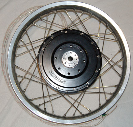

Some specs
Two turn winding motor
Power output: 10KW continuous @ 25c ambient temperature
Protection: thermally protected with kelly controller
Typical Voltage needed:
72 volts for 45 MPH with 18 X 3.5 tire
96 volts for 60 plus MPH with 18 X 3.5 tire
Typical current demand:
At 72 volts and 45 MPH < 50 amps
At 96 volts and 60 MPH < 95 amps
or
Three turn winding motor
Power output: 10KW continuous @ 25c ambient temperature
Protection: thermally protected with kelly controller
Typical Voltage needed:
72 volts for 30 MPH with 18 X 3.5 tire
96 volts for 45 plus MPH with 18 X 3.5 tire
Typical current demand:
At 72 volts and 30 MPH < 33 amps
At 96 volts and 45 MPH < 50 amps
You have to expect you can push them alot harder than 10,000watts. 200 amps at 96V should get you throwing some dirt around.
Perhaps an option for your motorbike build, if you can get one. $1300
Yeh I know I wasn't even considering an x5 or an x6. I Beat that crap out of my bike and I will probably use a engine in the frame with a chain drive to the rear wheel. I want the unsprung weight as low as possible and the engine up out of the water as much as possible. What is truly needed is a water cooled brushless motor that is sealed and the a radiator to cool. This will keep it alot cooler and keep the mud out! Wished someone would hire me to design it!bikeraider said:Arlo,
I have read you post about your motocross project. The only motor i can recommend for it, is a Marcycle hub motor or a Agni reinforced motor, you need a lot of power to turn a motocross wheel and tires. Any X5 is not power enough for this usage like i have experiment with my electric dirt bike and my X5304.
Good day!
Bikeraider
The X5 I have coming is for my bmx because I have too much work and money left to build my giant outer runner bmx wheel at the moment!
Man I wished Crystalyte would learn their spokes, rims, and hubs would last alot longer if they would just use a crossed lacing pattern!Kiwi said:Crystalyte build this plug and play motor for a company called EnerTrac. http://www.doingitall.net/EnerTrac/index.php 10,000watt.
bikeraider said:Hi Methods,
I think the correct value for the shunt is around .0320 mOhm on the high range mode. If it's right i only have the wrong value on the CA.
Thanks good day!
Bikeraider
Bikeraider, the shunt will be around 320 uOhms (micro-ohms). That is 0.32 mOhms. Final calibration will be needed after this best guess setting.
methods
1 GW
You have to enter the value that you measure from your specific shunt.
You will need to be in High Range mode.
When you switched to high range mode the value that popped up there is nonsense.
Your shunt value will be between 0.250 mOhms (250uOhms) and 0.350 mOhms (350uOhms)
In the CA it will read like:
.2700
But - you must not just put a value in there as a guess. You have to calibrate your shunt.
Search for my post on calibrating shunts using the iCharger. It is very easy and you can do it without opening hte controller.
Basically you drive a constant 10A in to the GROUND wire and out of any of the 3 PHASE wires.
This will drive -10A through your shunt. You can read the value on the CA then use the percent different formula and successive approximation to calibrate.
Usually takes 2 - 3 iterations.
-methods
Similar threads
- Replies
- 3
- Views
- 3,158
- Replies
- 0
- Views
- 908
- Replies
- 21
- Views
- 4,243
- Replies
- 142
- Views
- 52,779
- Replies
- 28
- Views
- 12,112