Hyperelectronic
1 µW
Hello all of you,
Short introduction from my side, I am an electrical engineer / electronics developer / firmware programmer from Austria who likes to deal with all kind of electrical components / electronics / battery storage systems ranging from very small power levels (uCs) up to very large ones (EVs). I also over the years have gained a lot of experience in the field of reverse engineering.
Currently I am working on reverse engineering the "Embedded Telecom Power" (ETP) modules from Huawei to get them working standalone and I already managed to get the rectifier modules fully working (complete remote control, status communication, diagnostic data (including fan management) via can bus, etc.) and currently already use them to charge my powerwall with the excess power of my solar system (3x R4875G1 modules connected to 3 phase ac power and managed by a central ESP32 board with fully automated load management / power control). Additionally I also have the super high efficiency variant of this modules (R4850S1) for testing purposes.
I am now working specifically on the inverter type of modules but simply can not get them to work so far. I tried measuring and manipulating all possible data signals on the connector, but can not get it to communicate via can bus and therefore can not control it / enable the output.
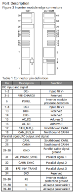
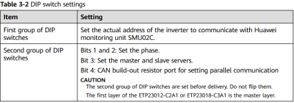
I already found out, that this kind of module seems to do not have the auto addressing functionality that the rectifier modules have and therefore need static addressing (set via resistors, which I could not exactly determine because I do not have an original enclosure for it, but by a bit of trial and error found a combination where the module does not simply signal an slot error but still no communication is possible)
The main problem is, that there is zero communication comming from the module (as there is with the rectifier modules), also sending a lot of different messages to it made no difference, I even tried to brute force it, but with 29 bit of possible addresses and a nearly infinite amount of possible data combinations, there is really no big chance to get it working this way. I tried the northbound and southbound can bus at different states at the other pins, I am also 100% sure the whole communication chain is working properly, as if i plug a rectfier module into the same connector everything is working perfectly and with both types of modules only at the correct 125 kbit/s there is no immediate can bus error if I send messages to it.
The last thing I did is let the GPT do a deep resarch but that also did not result in anything useful. The only reference I got are some videos of a guy (on a chinese video platform) that seem to be a engineer at huawei and he has posted some short videos on the module working externally (from the comments it seems to be very likely that it was done with some special firmware on it).
I believe there must be some kind of unlocking sequence build into it (I am not sure if it is implemented in hardware via pins or software via can bus) or if it is only to protect people from mains output voltage or to lock us out from using it externally.
So the only way and hope I have, is you guys, as I am currently quite stuck.
Does anyone of you have an ETP23003 or ETP23006 enclosure and can reach out to me, so we can do a few measurements? (I think we will be able to get it working in a very short time)
I also have a lot more detailed informations / measurement values and images of the electronics of the modules that I could / will provide if needed, but as I am always very bussy, I do not have a lot of time for documenting it online in detail.
Thanks a lot to all of you in advance!
Short introduction from my side, I am an electrical engineer / electronics developer / firmware programmer from Austria who likes to deal with all kind of electrical components / electronics / battery storage systems ranging from very small power levels (uCs) up to very large ones (EVs). I also over the years have gained a lot of experience in the field of reverse engineering.
Currently I am working on reverse engineering the "Embedded Telecom Power" (ETP) modules from Huawei to get them working standalone and I already managed to get the rectifier modules fully working (complete remote control, status communication, diagnostic data (including fan management) via can bus, etc.) and currently already use them to charge my powerwall with the excess power of my solar system (3x R4875G1 modules connected to 3 phase ac power and managed by a central ESP32 board with fully automated load management / power control). Additionally I also have the super high efficiency variant of this modules (R4850S1) for testing purposes.
I am now working specifically on the inverter type of modules but simply can not get them to work so far. I tried measuring and manipulating all possible data signals on the connector, but can not get it to communicate via can bus and therefore can not control it / enable the output.
I already found out, that this kind of module seems to do not have the auto addressing functionality that the rectifier modules have and therefore need static addressing (set via resistors, which I could not exactly determine because I do not have an original enclosure for it, but by a bit of trial and error found a combination where the module does not simply signal an slot error but still no communication is possible)
The main problem is, that there is zero communication comming from the module (as there is with the rectifier modules), also sending a lot of different messages to it made no difference, I even tried to brute force it, but with 29 bit of possible addresses and a nearly infinite amount of possible data combinations, there is really no big chance to get it working this way. I tried the northbound and southbound can bus at different states at the other pins, I am also 100% sure the whole communication chain is working properly, as if i plug a rectfier module into the same connector everything is working perfectly and with both types of modules only at the correct 125 kbit/s there is no immediate can bus error if I send messages to it.
The last thing I did is let the GPT do a deep resarch but that also did not result in anything useful. The only reference I got are some videos of a guy (on a chinese video platform) that seem to be a engineer at huawei and he has posted some short videos on the module working externally (from the comments it seems to be very likely that it was done with some special firmware on it).
I believe there must be some kind of unlocking sequence build into it (I am not sure if it is implemented in hardware via pins or software via can bus) or if it is only to protect people from mains output voltage or to lock us out from using it externally.
So the only way and hope I have, is you guys, as I am currently quite stuck.
Does anyone of you have an ETP23003 or ETP23006 enclosure and can reach out to me, so we can do a few measurements? (I think we will be able to get it working in a very short time)
I also have a lot more detailed informations / measurement values and images of the electronics of the modules that I could / will provide if needed, but as I am always very bussy, I do not have a lot of time for documenting it online in detail.
Thanks a lot to all of you in advance!