dogman said:
since a photovotaic roof is a higher priority

Solar is good preparation for the future, as is any personal power generation. Did you see my post in 'general' on these motorwave microturbines I am trying out? Very cool concept, supposedly effective in light winds, but the company

was difficult to work with:

dogman said:
Some of the EV bloggers do like to exaggerate the results of thier build.
I really hope to not do that, but I have to admit that I want the weight savings of Headway's LiFePO4 to translate into reduced battery requirements, so I am biased. I am trying to be vigilent and stick to facts; I also want to generate very specific WPM info so anyone following in my footsteps will have LiFe chemistry-specific results to base their builds on, it has been a real challange to engineer this without similar builds to compare it to. Accordingly, here are today's test results I went for an early-morning (pre traffic!) cruise to evaluate my watts per mile. I live in a moderately hilly area, so the results are real-world, not flat-surface. The video is below.
[youtube]tYd7jSsM5ZQ[/youtube]
When Justin first introduced the CycleAnalast I bought a beta version of the Jumbo Cycleanalyst (6-wire), specifically for the day I would do this bus conversion. I connected the V+ wire to the battery + contactor. I connected the signal to the controller side of the shunt, and both grounds to the battery - side of the shunt. The shunt is a .50ma/500a, so I configured the shunt resistance in advanced settings as 0.5000 .
Because any of these long 15' 20ga wires could short a huge amount of current and catch fire, I put a polyfuse on all three leads right where they connect. question: Could the polyfuse, and the resistance of the long thin wire, change the resistance and affect the cycleanalyst's readings?
The CA is configured in high-current mode. I am assuming that when I see 50.1 it is really drawing 501 amps, does that sound right? There were a few times it spiked up to 60.x, but my 400a Silicon fuses didn't pop, and Steven at Kelly assured me that the 500a controller would never draw more than 400a, so I think I didn't do something right.
Under peak load the 16-cell array was around 47v, or 2.937v/cell. This corresponds with about 3c on the discharge testing curves for the cells, or 240a on this 80ah pack.
I realized afterwards that I didn't check how many watt-hours the cruise consumed. When I powered the CA back on, I discovered that this version isn't saving data - not sure if it is a beta-bug or my wiring. I went and redid the cruise, this time the bus seemed a bit faster, but the tranny/transaxle fluids I pupt in 6+ years ago were way too viscous, and with the ICE I noticed it was faster after they heated up. I need to replace both of these with a lightweight synthetic.
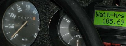
I adding an extra block for the second cruise to exceed a full mile - and took the start/finish pictures below. If I have the the CA configured correctly, then it turned 100wh right around the 1 mile point. Since it was so slow, I figure this is what it takes to actually move the bus over that distance, and that additional current consumed will be to overcome drag.
On uphills the bus didn't want to go more than 15mph, which was disappointing but I should have expected that from 48v. Now I am wondering if I should go straight to 120v instead of 90v, even though that means building a second battery tray.
-JD
EDIT 12/14/12: replaced pictures lost when the forum crashed a few years ago.
View attachment 2


