wyvernwaddell
1 W
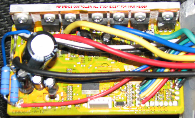
Anyone know what the phase and halls would be for a BMC V4C to a 12 fet infineon controller from Grin Cyclery http://www.ebikes.ca/store/store_controllers.php. This one-C7240-NC .
Interesting. Now I know why my Xoingda at 8:1 in low gear starts off pretty well. High is about 4:1 and also starts off fairly well.Thanks and now back to our regularly scheduled topic.motomech said:Standard Q100 (8.1:1 reduction ratio) w\ Grin\Infineon 6-FET.
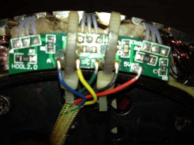
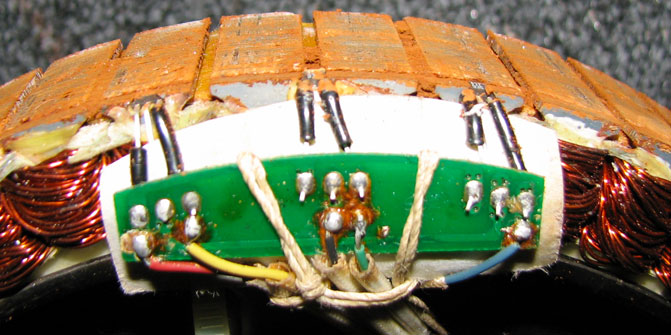
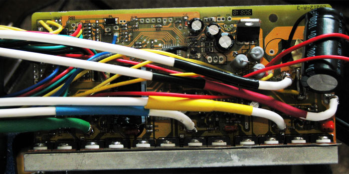
Phase; all colors match.
Halls; all colors match

alsmith said:You did connect the ignition wire? (no disrespect- it has happened!). Otherwise go through the diagram posted above (by Kiwi » Fri May 24, 2013 1:43 am). When you find the right combination please post it here for the general knowledge as someone else may have the same issue at some time. Cheers.
Connect it to your battery positive. Can be permanent connection, or you can use a switch or keyswitch to use it to disable/enable your controller.timeride said:now that I have identified the ignition wire- how do I "connect" it? ie I by a single pole throw switch? and just run a lead to an earth?
timeride said:alsmith said:You did connect the ignition wire? (no disrespect- it has happened!). Otherwise go through the diagram posted above (by Kiwi » Fri May 24, 2013 1:43 am). When you find the right combination please post it here for the general knowledge as someone else may have the same issue at some time. Cheers.
I too was thinking this may have been the fundamental problem- no power to the circuit. Ok, I'm sounding really, really stoopid here in front of an audience of experienced electrical circuit builders, but, now that I have identified the ignition wire- how do I "connect" it? ie I by a single pole throw switch? and just run a lead to an earth?
I did a bit of digging on this and looks like the Micah e-bike school website recommends installing a relay as well for current over 20a (I have 15a/h batteries, so I may be able to get away without a relay)
Thanks for any assistance!