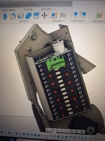
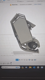
Thanks, lots of preparation and ordering parts thus far but now that most of the parts have arrived I be starting the real work. Time to build!Very nice project
KTM conversion ELXC
- Thread starter bunya
- Start date
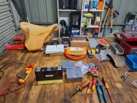
Confirming the battery design with 0.5mm 3040 epoxy glass sheet insulators between cells, thanks @amberwolf
I've found that most electrical insulation/mechanical padding materials generally have poor thermal conductivity.
I know I'll be dropping the bike when off road and the battery enclosure will likely take some damage being mounted on the sides of the frame. The risk of the aluminium enclosure shorting against the cell terminals or damaging the cells is something that has been on my mind.
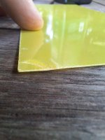
To protect against this I've opted to use 2mm thermal pad on each side of the pack to conduct heat away from the cells as well as providing some space to absorb any small dents from damage. I also did some destructive testing of the 3040 epoxy glass sheet to see how it would absorb damage from a cell terminal pressing hard against if that happened in a crash. I expected it to crack like fibreglass but it held up really well to a few solid blows from me hitting it with a hammer. I'll use this above the terminals on the lid of each 14s battery case. I'd recommend this if other members are looking for a strong, thin (0.5mm) insulator.
Last edited:
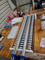
I've been testing the compression/immobilisation with some sash clamps and the 0.5mm fibreglass sheet between each cell. The spec sheet I have from the CALB 58Ah NMC states 100kgf, this is more than Iexpected and these 75Ah cells have approximately 50% more side surface area. My compression force may need to be increased to 150kg. I'll check with the manufactured on their requirement.
I'm not sure if others in this forum have experience with compression of prismatic NMC cells so hopefully this will be useful information for others building similar packs.
I've also started making the 26 bus bars from 3mm x 22mm wide copper flat bar.
One milestone for the project was dropping the bike off at Spartan Future for the design, fabrication and engineering approval of the battery cases and motor mounts. This is a requirement for getting the bike's modification approved for road registration.
The fork and shock also came back from a service and were put back into the bike. It feels super plush now!
Next steps are to configure and bench test the battery, BMS and charger including the CANBUS implementation on the display.
I'm not sure if others in this forum have experience with compression of prismatic NMC cells so hopefully this will be useful information for others building similar packs.
I've also started making the 26 bus bars from 3mm x 22mm wide copper flat bar.

One milestone for the project was dropping the bike off at Spartan Future for the design, fabrication and engineering approval of the battery cases and motor mounts. This is a requirement for getting the bike's modification approved for road registration.
The fork and shock also came back from a service and were put back into the bike. It feels super plush now!
Next steps are to configure and bench test the battery, BMS and charger including the CANBUS implementation on the display.
Cali Yang
1 mW
Is there any latest news?For those who would like to see the test results I received from the manufacturer I have attached them to the post. From my perspective the results look reasonable but I don't have much experience purchasing NMC cells. Variation in capacity of 1.3Ah/1.8% and IR of 0.02mOhm/4.3%. Keen to hear from the group if these match people's expectations for A grade cells.
Deligreen (TC Elcon) 2kW charger has also arrived. Has an additional 12V supply and output contacts but I haven't figured out the exact use for them yet. I may use the 12V supply and contacts as part of the fail safe circuit for if the CANBUS locks up and the BMS needs to disconnect the charger. Max charger voltage is set to 117.6v.
View attachment 350047
I'll post up some news on the bms and battery once I start bench testing, hopefully this weekendIs there any latest news?
I did have a question about the mounting of the LV bms with regard to the 500A rating. I note that the MAXKGO version terminates the cable lugs on the top of the PCB rather than directly on the contactor and shunt as per the ENNOID design. This requires the current to flow through the PCB.
I noticed there were no through hole vias but I wasn't sure if the PCB pads/terminals were sold copper inserts. Could you confirm if it would be preferable to mount the cable lugs to the underside of the shunt to reduce PCB heating?
Cali Yang
1 mW
If it is installed on the front, the current will pass through the screw column to the shunt path. If it is installed on the shunt, the current will flow directly through the shunt. There is nothing wrong with either, but it seems that installing it directly on the shunt is also good.I'll post up some news on the bms and battery once I start bench testing, hopefully this weekend
I did have a question about the mounting of the LV bms with regard to the 500A rating. I note that the MAXKGO version terminates the cable lugs on the top of the PCB rather than directly on the contactor and shunt as per the ENNOID design. This requires the current to flow through the PCB.
I noticed there were no through hole vias but I wasn't sure if the PCB pads/terminals were sold copper inserts. Could you confirm if it would be preferable to mount the cable lugs to the underside of the shunt to reduce PCB heating?
Engineering gifs are what's up.Design is at 90%View attachment 353794
We're getting serious with the engineering formalities and finite element analysis (FEA).
This assessment is part of the approvals process in Australia, and assists in validating and improving the safety of the build.

I have ordered what I hope is all the remaining parts for the ancillary circuits. This is a part of the build that took considerable time and I had to do my own research rather than just copying other designs. I have made use of panel mount Chogori type M23 connections for the charge and power supply/DC-DC converter circuits and have used PV DC fuses to protect the smaller cables.

I've taken a punt with a cheap 40A solid state relay to control the charge circuit in tandem with the CAN1430 charger protocol (redundant).
Smaller comms cabling and 12V signals are connected through the panel mounted SP16 connectors shown below.
This assessment is part of the approvals process in Australia, and assists in validating and improving the safety of the build.

I have ordered what I hope is all the remaining parts for the ancillary circuits. This is a part of the build that took considerable time and I had to do my own research rather than just copying other designs. I have made use of panel mount Chogori type M23 connections for the charge and power supply/DC-DC converter circuits and have used PV DC fuses to protect the smaller cables.

I've taken a punt with a cheap 40A solid state relay to control the charge circuit in tandem with the CAN1430 charger protocol (redundant).
Smaller comms cabling and 12V signals are connected through the panel mounted SP16 connectors shown below.

Last edited:
The battery design has passed the NCOP14 FEA using 5052 H32 aluminium.
I've added some final touches to keep the motor more supported when under load.
This includes the mount to the swingarm shown above and doubling the face mounting plate to 8mm thickness.
Will be requesting approval from the signatory engineering and starting fabrication this week.
For those who aren't aware fusion360 is free for non commercial use and has a lot of good support content online. I'd recommend it for those who want to have a go at CAD. You'll need the commercial version for FEA though. I haven't played with this type software since highschool, it's much easier to use these days.
I've added some final touches to keep the motor more supported when under load.

This includes the mount to the swingarm shown above and doubling the face mounting plate to 8mm thickness.
Will be requesting approval from the signatory engineering and starting fabrication this week.
For those who aren't aware fusion360 is free for non commercial use and has a lot of good support content online. I'd recommend it for those who want to have a go at CAD. You'll need the commercial version for FEA though. I haven't played with this type software since highschool, it's much easier to use these days.
which seller did you use mate? and what composition are they?The cells arrived much sooner than expected. Now it's time for some bench testing!
View attachment 352357
The spec sheet says they are NMC613 composition and I bought them direct from the manufacturer Shenzhen Westart, they were very good to deal with. I did need to pay via a wire transfer but I validated the invoice with them and there were no issues.which seller did you use mate? and what composition are they?
I had a look through Alibaba but most vendors there were offering batches of cells that larger manufacturers like CATL or CALB had rejected so I wasn't super keen.
I also had my mind set on the two sided battery design because I wanted to be able to remove them and put them in a parallel to power an electric tinny.
Balance wires all combed, measured up and terminated. Each 14s pack is the same arrangement so I can measure twice and cut twice!
We will be bench testing tomorrow

The sheetmetal will hit the laser cutter this week.
I did one last panel out of aluminium to mount the controller to. It will replace the air box cover and serve to increase both the controller's thermal mass and ability to lose heat. I have a feeling the EM260 will run hot at 350A, especially with the 96V (135V) mosfets. I also bought a heatsink which I can retrospective fit to the panel if I need extra old school aircoolong fins.
There are two more bends toward the top right of the panel that I haven't drawn. I used a cardboard stencil to fit the space in the frame manually and have kept the drawing mostly 2D.
This is how the design has ended up minus a couple small changes to the battery mounts.
We will be bench testing tomorrow

The sheetmetal will hit the laser cutter this week.
I did one last panel out of aluminium to mount the controller to. It will replace the air box cover and serve to increase both the controller's thermal mass and ability to lose heat. I have a feeling the EM260 will run hot at 350A, especially with the 96V (135V) mosfets. I also bought a heatsink which I can retrospective fit to the panel if I need extra old school aircoolong fins.

There are two more bends toward the top right of the panel that I haven't drawn. I used a cardboard stencil to fit the space in the frame manually and have kept the drawing mostly 2D.
This is how the design has ended up minus a couple small changes to the battery mounts.

Last edited:
More progress today with benchtesting the Maxkgo/Ennoid BMS. I uploaded a base configuration and tested discharge control, and some fault codes when I didn't have the coil wired in.
All the cells look nicely balanced from the factory too with only 0.002V difference between them.
I'm really appreciating the effort that was spent to develop the Ennoid software, it meets all my immediate needs and is configurable if/when I want to change the battery configuration from 28S1P to 14S2P for another purpose.
Tomorrow I'll have a crack at the CANBUS charger control and using the CAN enable pin to externally control the BMS from a key switch.
The guys at Spartan Future have laser cut the battery boxes and some of the motor mounts ready for the press brake and TIG.

All the cells look nicely balanced from the factory too with only 0.002V difference between them.
I'm really appreciating the effort that was spent to develop the Ennoid software, it meets all my immediate needs and is configurable if/when I want to change the battery configuration from 28S1P to 14S2P for another purpose.
Tomorrow I'll have a crack at the CANBUS charger control and using the CAN enable pin to externally control the BMS from a key switch.

The guys at Spartan Future have laser cut the battery boxes and some of the motor mounts ready for the press brake and TIG.

Last edited:
peadar
100 W
Could you link to thermal pad2mm thermal pad on each side of the pack to conduct heat away from the cells
I used the 200x400x2mm sheet:Could you link to thermal pad
RGeek 6.0W/mK Thermal Pad
It is quite soft so I will use it in combination with 2mm neoprene/rubber strips around the corners where the battery case might hit rocks when I drop it off road.
Well we've hit a small snag with the charger. For some reason it doesn't want to produce voltage after the CAN BUS handshake. 
I haven't been able to sniff the CAN traffic but I have noted that when the baud rate is set to 250kbps the BMS detects the charger, enters the charging state and energises the charge relay coil. When set to 125kbps or 500kbps the BMS remains in its default discharge state.
So I assume the BMS is detecting the CANBUS message from the charger correctly but unfortunately there is no voltage at the charger terminals. I have noted there is an unused plug with two pins that aren't on the charger. I'm thinking it may have its own internal relay coil and which isn't energised. If anyone has experience with the CAN1430 TC/Elcon chargers I'm all ears.
I also blew the 2A fuse for the DC-DC converter, it had much more capacitance and inrush than I expected... I will have it always connected to the pack but will need to manually precharge it before connecting it with my spare 2A fuse. Hopefully I didn't blow up the converter trying to turn it on lol.
Last edited:
Well with a manual precharge using a 5W 27Ohm resistor and a pair of insulated pliers the DC/DC converter is now powering the BMS, success! Parasitic draw from the converter is approximately 5W, which is a bit higher than I expected. I'll need to remove the fuse when not using the bike for extended periods and make sure I keep and eye in SOC on a monthly basis. If I get too paranoid about it I'll need to re-design the 12V circuit to charge from the load circuit and install a separate 12V battery. For now I'll keep it as is and measure the space I have left once the controller is installed where the battery used to live. I don't think there will be much space left...
I've message the vendor to confirm the charger settings and to see if I've missed anything.
I also made a realisation that you can't use a solid state relay on the Ennoid BMS is you are using a CC/CV charger. The diode within the SSR gives voltage to the charger terminal regardless of if the charger is on or not. If you then switch the polarity of the wiring the SSR will never disconnect the charger from the battery as it will flow through the diode...
Luckily for my implementation I am using CANBUS so the charger voltage is communicated over CAN1430 rather than measure as an analog value.
We have the battery boxes folded up ready for welding!

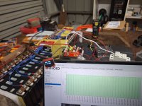
In regards to the CANBUS and charger issue I have started programming my adafruit CAN shield and 3.5" display to sniff the CAN traffic from both the BMS and Charger to determine why the charger isn't supplying voltage once the BMS closes the charge circuit. The canio circuitpython is pretty easy to get started with so should point me to the issue.
The vendor confirmed the max voltage of the charger is correctly set to 117.6V (4.2V per cell).
So, I have been able to sniff the CAN BUS and check the values against the charger CAN dbc file: GitHub - karlding/elcon-charger-dbc: CAN DBC file for an ELCON UHF charger
To decode the stream I used the online tools from DBC Editor for CAN Bus Database Files [Online | 100% Free].
The charger is data: \x049\x00\x97\x10\x00\x00\x00 which aligns with the CAN1430 standard but I have an issue with the first byte which is 049, this is greater than the max allowable two hexadecimal digits.
If I take the value as 04 it is 102.4V as below:

If I use 49 its 1868.6V ....
On the flip side the BMS is reporting data: '\x04m\x00\x96\x00'
I have no idea why and ascii character 'm' is appearing in the hexadecimal stream.
But if I drop the 'm' and use the '04' the value is the same as the charger.
The problem is that my pack is already at 108V so 102.4V isn't going to cut it. I don't normally believe in co-incidence but 102.4/28 is 3.657V which is very close to the limit I would expect from an LFP pack. I may change some settings in the BMS to see if this changes the value over CAN BUS.
If anyone has experience with CANBUS I'd appreciate any input or pointers.
I am getting other messages for BMS data with ascii characters to for example: '\x04m\x01\n\x00', '\x04l\x01\r\x00'
To decode the stream I used the online tools from DBC Editor for CAN Bus Database Files [Online | 100% Free].
The charger is data: \x049\x00\x97\x10\x00\x00\x00 which aligns with the CAN1430 standard but I have an issue with the first byte which is 049, this is greater than the max allowable two hexadecimal digits.
If I take the value as 04 it is 102.4V as below:

If I use 49 its 1868.6V ....
On the flip side the BMS is reporting data: '\x04m\x00\x96\x00'
I have no idea why and ascii character 'm' is appearing in the hexadecimal stream.
But if I drop the 'm' and use the '04' the value is the same as the charger.
The problem is that my pack is already at 108V so 102.4V isn't going to cut it. I don't normally believe in co-incidence but 102.4/28 is 3.657V which is very close to the limit I would expect from an LFP pack. I may change some settings in the BMS to see if this changes the value over CAN BUS.
If anyone has experience with CANBUS I'd appreciate any input or pointers.
I am getting other messages for BMS data with ascii characters to for example: '\x04m\x01\n\x00', '\x04l\x01\r\x00'
Last edited:
I've decided to use CircuitPython to further debug the CAN bus between the BMS and the charger. The results are much more aligned with what I would expect, especially from the BMS.
Upon connection the BMS is requesting 113.2V@5A and its control bit has status "charger starting up to charge".
Unfortunately the charger isnt quite right. It is reporting the correct terminal voltage of 108V but the current is being reported as 15.1A further the status bit is 16 (2^4) indicating the 4th bits status is 1. This corresponds to "Communication receiving time-out"

So the charger isn't receiving the messages from the bus. If my basic CircuitPython tool can correctly decode the CAN bus I see no reason why the charger wouldn't be working. My only concern is that the charger is 2 wire and that I may need to connect a ground reference. I will await a response from the vendor to determine my next steps.
@PK2000 You were right! I thought this standardised protocol would be plug and play. I wouldn't describe sniffing CAN traffic as play
Upon connection the BMS is requesting 113.2V@5A and its control bit has status "charger starting up to charge".
Unfortunately the charger isnt quite right. It is reporting the correct terminal voltage of 108V but the current is being reported as 15.1A further the status bit is 16 (2^4) indicating the 4th bits status is 1. This corresponds to "Communication receiving time-out"

So the charger isn't receiving the messages from the bus. If my basic CircuitPython tool can correctly decode the CAN bus I see no reason why the charger wouldn't be working. My only concern is that the charger is 2 wire and that I may need to connect a ground reference. I will await a response from the vendor to determine my next steps.
@PK2000 You were right! I thought this standardised protocol would be plug and play. I wouldn't describe sniffing CAN traffic as play
With some help from the Spartan Future fellas, I was able to get to the root cause of the CAN bus issue. It turns out the charger cannot accept data packets less than 8 bytes!
The Ennoid implementation dynamically sizes the data packet depending on what is being sent. For BMS and Discharge data this varies between 4 and 8 bytes.
For the charger function it only needs to send 5 bytes but the charger needs the last three bytes padded out to 00 00 00. We did this using a CAN tool and it started right up!
It looks like I'll need to go to the ennoid source code to resolve this issue and compile the firmware with a different CAN dbc with those extra bytes. At least I know what the issue is...
In other news the welding is complete and I can now commence assembly of the 14s packs.

I also need to decide on what I'm doing for the colour/painting.
The Ennoid implementation dynamically sizes the data packet depending on what is being sent. For BMS and Discharge data this varies between 4 and 8 bytes.
For the charger function it only needs to send 5 bytes but the charger needs the last three bytes padded out to 00 00 00. We did this using a CAN tool and it started right up!
It looks like I'll need to go to the ennoid source code to resolve this issue and compile the firmware with a different CAN dbc with those extra bytes. At least I know what the issue is...
In other news the welding is complete and I can now commence assembly of the 14s packs.

I also need to decide on what I'm doing for the colour/painting.


