KTM conversion ELXC

bunya

10 W
Joined
Mar 12, 2015
Messages
65
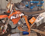
Kicking off a build thread on a 2010 KTM EXC

Objective is to have a road registrable e-moto that can be used for commuting and to have fun off road. I'm based in Darwin, Northern Territory, Australia.

Build List:

Motor: QS 138 90h V3 mid drive with 2.35:1 reduction

Controller: Votol Em260s 96V with CAN BUS

Battery: 28s NMC prismatic split into two 14s packs for each side of the frame. Cells are Westart 75Ah 6C NMC.

BMS: MAXKGO hardware of the ENNOID V1 Master-Slave BMS with EVC 500 contactor and two 15s slave boards. I'll also have a 400A HRC fuse for backup protection.

Display: I'm undecided on the display. I've ordered the controller with CAN Bus so I have the option combine the BMS and controller CAN data on the open source display such as GitHub - dsoto/VESC-Ennoid-CAN-Feather.
To achieve this I would need to branch/fork the code and add an option include the Votol CAN implentation in addition to the VESC library.

I'm in the planning phase but have received 'in principle' approval from the vehicle registry Technical Advisory Committee for the conversion. I will require engineering approvals and compliance checks before the bike can be registered.

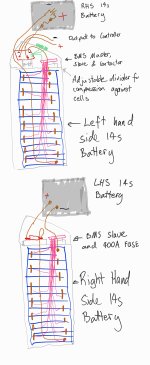
Initial cardboard aided design attached.20240129_153533.jpg
 
Last edited:
Battery: 28s NMC prismatic split into two 14s packs for each side of the frame. I'm leaning towards the 72Ah high discharge CATL cells but depending on availability may settle on the CALB or EVE 58Ah cells.

Make sure to leave space for the compression packaging to keep the cells all flat. Without it the cells can swell in use and delaminate, negatively affecting their characteristics and performance. Should be some examples in my posts if you look for "compression".
 
Make sure to leave space for the compression packaging to keep the cells all flat. Without it the cells can swell in use and delaminate, negatively affecting their characteristics and performance. Should be some examples in my posts if you look for "compression".
Thanks, I'll be making each 14s battery enclosure out of 2mm (5/64") aluminium with the ability to apply compression to one end of the battery stack. I have read some of your examples and will post up a design of the battery box shortly. I'm a little concerned about the current leakage between individual cells if/when the thin PVC coating wears through against the battery box, I'm going to see if some thin silicone sheet can be used to maintain isolation.
 
If the cells are properly immobilized in the compression enclosure, they can't rub on it. ;)

But if you want something as an insulator, I'd use FR4 board; it comes in various thicknesses.
 
The Fardriver 96680 has a max working voltage of 115v. 4.2v x 28s = 117.6v. Sure you can keep your max charge to 4.1v, for 114.8v max voltage, but that's cutting the operating voltage real close to its specs, for my liking. Is that okay with your build?
 
If the cells are properly immobilized in the compression enclosure, they can't rub on it. ;)

But if you want something as an insulator, I'd use FR4 board; it comes in various thicknesses.
Rough sketch for the split packs. Thanks, I'll add some of that fr4 board around the edges.
Battery sketch.jpg
 
The Fardriver 96680 has a max working voltage of 115v. 4.2v x 28s = 117.6v. Sure you can keep your max charge to 4.1v, for 114.8v max voltage, but that's cutting the operating voltage real close to its specs, for my liking. Is that okay with your build?
Yeah, I wasn't sure how much buffer was built into the 28s ternary lithium battery maximum limit set in the fardriver manuals. I've read others on the forum using 28s on the nd96xxx controllers and noted the youtube teardown of the nd96530 shows the controller using 135V fets and 120V caps. I don't want to restrict charging to only 4.1V if that results in losing more than 5-10% of the pack capacity. Do you know what the 115V limit represents or have you experienced controller failures when running at 28s. Thanks for the heads up, I don't want to build this to smoke the controller on the first ride. Here is one reference to ND96xx series:
Post in thread 'Nanjing far driver controllers' Nanjing far driver controllers
 
Last edited:
I don't personally have the controller, no. I just don't trust spec sheets and try to leave a decent margin in my builds. I'm sure it's possibly to run it at 28s. Regularly and consistently without fault? Couldn't say. If it was my build id get something that's rated for 150v
 
The Fardriver 96680 has a max working voltage of 115v. 4.2v x 28s = 117.6v. Sure you can keep your max charge to 4.1v, for 114.8v max voltage, but that's cutting the operating voltage real close to its specs, for my liking. Is that okay with your build?

Bunya. I would go with what Harrison said.
 
I ran my 961800 up to 120,5V for a year or so. Not that I recommend it, but it didnt break for me.
I woldnt hesitate to run it at 28s, but of course it is a question of what risk you are willing to take.
Thanks for sharing, I'm willing to take some risk for sure, but I don't think I'll go to 120.5V to begin with haha. I'll start with 4.15V/cell and low regen current and work my way up as I can monitor and get comfortable with it. The controller is probably a little small for a full size dirtbike and I may upgrade to a 3shul or larger model in the future.
 
No, I think 120,5V (the controller read it as 121,5, and would cut out if I went 0,1v higher) is just foolish. I did it because I had 30s and couldent get a 1081800, or any controller in the 108v line really.
I just wanted to mention it as an example that it probably wont break as soon as you run it anywhere near the limits, but it is up each one how safe you want to play.
 
Few more updates:

ND96680 controller has been ruled out due to the updated version now being limited to 250 battery amps. I'll continue to run the 28s on the ND96890 (410BA).

As with all builds the design needs to strike the right balance of range, power and weight. I've set a limit of 130kg which I'll try keep to but some of the local guys in Darwin have urged me to up the battery to over 8kWh to get closer to 100km if doing highway speeds. So I'm now considering upping the pack to 30s and running the 3shul cl700/1000. I'm keen the range people are experiencing for primarily commuting up to 80km/h.

I've read all the approval documentation and there isn't anything too tricky. The only engineering design signoff required is for the battery restraint. I'll try keep the battery box simple and less than 25kg each. The motor mount is not mine but a design I found from the Facebook 'Electric Motorcycle Builds'.
Battery Bracket.jpg


I'm going to try do away with the factory 12v system including battery to save a few kgs too. The contactor is normally open so the BMS will provide fail-safe protection without a 12V battery. I've bought an 8A isolated dc-dc converter for powering ancillaries and the BMS. I believe the Ennoid has a dedicated/always on power supply circuit for the dc-dc converter which is a smart feature.

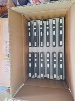
I've also decided on using the Westart 75Ah HEV 6C cells (attached) and once I've decided on 28s vs 30s will place the order. The alibaba suppliers could not source the 72Ah CATL cells I had initially planned for.

Next steps are to get an engineer engaged for the signatory approvals and ordering cells, motor, controller and charger!
 

Attachments

  • Westart HEV NCM75Ah specification V1.0.pdf
    454.6 KB · Views: 4
Last edited:
I'm going through the same (make it registerable in WA) process. You're going to need a separate 12V source. You have to be able to run the lights/hazards, with the main contactor out.
The other nasty is that frame welds have to be X-Rayed, but this might be a "soft" requirement depending on who's signing off on the build.
 
You're going to need a separate 12V source. You have to be able to run the lights/hazards, with the main contactor out.
I'll have to confirm but I believe the ennoid BMS is "always on" to the power supply unit circuit. So I should have the DC-DC converter providing 12/13.8V when the contactor is open. I did choose the 13.8V converter in the case that I needed the battery. Thanks for the heads up, I'll draw up the circuit and confirm the BMS will do the job.
The NCOP14 Clause 2.12 is the requirement I need to meet in the Northern Territory and it doesn't explicitly call for a 12v battery. Just energy to run hazards for 20 mins and to prioritise lights (when main contactor is open).
 
I'll have to confirm but I believe the ennoid BMS is "always on" to the power supply unit circuit. So I should have the DC-DC converter providing 12/13.8V when the contactor is open.
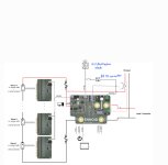
Something like this: EKATO CIRCUIT.jpg
 
I'll have to confirm but I believe the ennoid BMS is "always on" to the power supply unit circuit. So I should have the DC-DC converter providing 12/13.8V when the contactor is open. I did choose the 13.8V converter in the case that I needed the battery. Thanks for the heads up, I'll draw up the circuit and confirm the BMS will do the job.
The NCOP14 Clause 2.12 is the requirement I need to meet in the Northern Territory and it doesn't explicitly call for a 12v battery. Just energy to run hazards for 20 mins and to prioritise lights (when main contactor is open).
Ah, yes, I see your angle.. Interesting to hear how you go..
 
Orders have been placed for all the main parts:
  • 1.8kW CAN1430 96V charger
  • 28 x Westart 75Ah NMC cells
  • 4kW V3 QS
  • Votol EM260s 96V
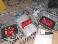
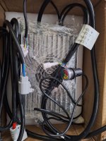
I've received the BMS and have confirmed the always on circuit for the power supply. Photo of BMS below:
20240301_195230.jpg

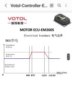
I took advice from the local EV conversion company "Spartan Future" that the Votol controller will provide better throttle response than the Fardriver so placed an order with them for that controller and the qs motor. I've include the way the controller treats over voltage below. 28s is definitely the upper limit but I'm going to see how it goes with cell voltage starting from 4V up.to 4.15V.
Screenshot_20240312_182245_Samsung Notes.jpg
The ancillaries are taking a surprising amount to time to design/source for fuses, charge circuit relays, CAN BUS connectors etc but I'm getting there steadily.

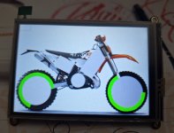
I'll order the Adafruit CAN feather and 3.5" display next and start designing the displays for charging, regular operation, battery and controller parameters.
 
For those who would like to see the test results I received from the manufacturer I have attached them to the post. From my perspective the results look reasonable but I don't have much experience purchasing NMC cells. Variation in capacity of 1.3Ah/1.8% and IR of 0.02mOhm/4.3%. Keen to hear from the group if these match people's expectations for A grade cells.


Deligreen (TC Elcon) 2kW charger has also arrived. Has an additional 12V supply and output contacts but I haven't figured out the exact use for them yet. I may use the 12V supply and contacts as part of the fail safe circuit for if the CANBUS locks up and the BMS needs to disconnect the charger. Max charger voltage is set to 117.6v.

20240326_172730.jpg
 

Attachments

  • Westart outgoing test report-28EA-NCM72AH.pdf
    171.7 KB · Views: 2
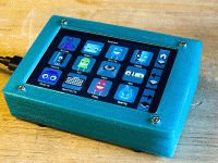
Most of my build doesn't push the boundaries of EV conversions, especially at Endless Sphere. The one area where I might be doing something of value to the community is with the display. I've ordered the adafruit 3.5" touchscreen and CAN feather to develop a display which I'll publish to Github. It'll give me something to work on while the cells make their journey from China to Australia.
3d_printing_touchdeck.gif
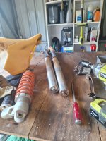
I've also decided to give the front and rear suspension a service.
20240331_101050.jpg
 
For those who would like to see the test results I received from the manufacturer...
First time I see single cell tests from a vendor or manufacturer. They look good.

I had tested 48 Eve C40 Lifepo4 sold as A cells from a vendor which tests every batch he buys.
They had IR tolerance +-4%.
The 105 pouch cells I have in my scooter are from two batches they had a total +-2.4% IR tolerance and in each batch +-1%.
 
Last edited:
I couldn't see many references to fuses for higher powered emoto builds on Endless Sphere so I'll add a link to the fuse I selected for my build. It's from a marine manufacturer and built by Bussmann here: Class T Fuse - 400 Amp - Blue Sea Systems

The fuse and fuse block are rated to 160V DC.
Sizes range from 225 to 400A and have a 20kA interrupt current at 160V DC which should fit the requirements of most builds.

I also found a super useful link from Eaton Bussmann for sizing fuses for EVs based on short term pulse usage here: https://www.eaton.com/content/dam/e...ehicle-application-guide-br132016en-en-gb.pdf

Its is quite large but there is also a smaller fuse holder for builds that are more constrained on space. The fuse terminates on a 150mm2 bus.
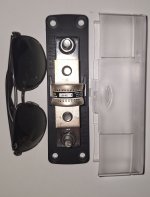
Image for size reference:

20240402_154425.jpg
 
Back
Top